Small geometries have projected IC technology into an era where test has become a crucial part in the chip design process and have introduced new challenges needing solutions that use already available resources. Currently, two distinct test methodologies are used to address the ever-increasing pressure to reduce the cost of manufacturing test, efficiently use test equipment, and increase yield.
One of the methodologies commonly used is logic built-in self-test (LBIST). LBIST technology inserts embedded logic for a self-contained test. It provides a fully integrated test solution that can be used at any test step or level of integration with a simple interface.
The logic insertion, problem logic fixes, and test points for high-quality test are fully automated. LBIST uses pseudorandom pattern generation (PRPG) and multiple input signature registers (MISRs), and detection of unmodeled faults is covered by using high multiple-detection pseudorandom vectors.
LBIST also reduces test time because shift is not limited by external data since patterns are generated on-chip using PRPG and the results are compressed into a final simple signature using MISRs. The LBIST solution also permits applying test at any level of configuration without an expensive, full tester environment. However, pseudorandom patterns might limit detection of some random resistant logic or specific pattern types.
Another methodology commonly used is ATPG. The main advantages of ATPG are high pattern efficiency due to use of deterministic patterns, low power support, high stuck-at coverage, and support for various fault models.
Regular ATPG has become a less efficient solution because of the amount of patterns required to test complex and large designs; however, embedded test compression technology allows scan test pattern application to be 100 times faster with fewer corresponding tester cycles. It also generates more patterns to target other fault models and reduces the test interface to just a few pins.
A switching activity threshold can be specified for both shift and capture cycles, and the ATPG tool will generate patterns to meet those limits. Other features were introduced recently, including the automatically inserted clock controller which bypasses the functional clock with a scan clock and creates a few at-speed clock cycles from a functional clock.
Using Both ATPG and LBIST
DFT engineers feel compelled to use one methodology exclusively; however, when considering the advantages and disadvantages of LBIST and scan test with embedded compression, they really complement each other.
By implementing a hybrid test methodology that combines LBIST and ATPG, the shortest test time is achieved while providing very high test coverage. A hybrid test solution allows the DFT designer to select one of these test methodologies or combine them for at-speed testing. These two methodologies enhance each other even if the techniques used to determine the faults, such as stuck-at, transition, bridges, or IDDQ, become more complex because of smaller technology nodes.
A hybrid test solution can use some features of one methodology to augment the other. Think of it as a hybrid car that uses a gas engine for power and an electric engine for higher mileage.
For example, shift speed of at-speed deterministic ATPG is limited by the shift path length from the primary I/O to the first flop or the length of the last flop to the primary I/O in addition to the speed of the pad I/O used. At-speed LBIST can help increase the speed of the shift clock because of the short shift paths between PRPG to the first flop and from the last flop to a MISR.
LBIST and ATPG also can complement each other when confronted with the limitation of LBIST to address a possible voltage drop caused by a high switching activity during design testing. At-speed deterministic ATPG can help resolve this problem by enabling low-power shift, which requires low-power embedded deterministic test (EDT) hardware to be implemented.
This will help the designer to lower the switching activity during test to match the switching activity of a mission mode. This switching activity is reduced during the load sequence of each test pattern by controlling the data shifted into the chains. The deterministic ATPG tool also is able to control the switching activity during capture by analyzing the clock of the design and finding all the functional clock gating cells that can be disabled during each test pattern.
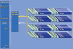
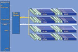
Figure 1. Structure of the LBIST-ATPG Hybrid Test Methodology
Hybrid test methodology allows the test engineer more flexibility to refine test implementation and optimally meet test requirements. In terms of chip size, a hybrid test methodology minimally affects area because the most common logic of these two at-speed test methodologies merges. As a result, the hybrid design has two distinct at-speed test methodologies with a small area impact.
In the hybrid test solution, the only logic that is not merged is the PRPG/MISR used for LBIST and the EDT logic used for deterministic ATPG. However, these pieces will be merged in upcoming tool versions. Figure 1 provides an illustration of hybrid test methodology structure.
LBIST-ATPG Hybrid Test Structure
The hybrid test methodology is based on the concept of core isolation, which allows two overlapping modes: external and internal.
In the external mode, only the block interface/peripheral registers are connected to dedicated chains. The remaining registers, which are the core registers of the block, are not part of these external chains during the external mode.
The internal mode incorporates all scannable registers of the blocks inside multiple chains, including the peripheral registers. To fully isolate the block from external logic, the input interface registers are kept in shift-only mode so they do not capture unknown values from the upper level.
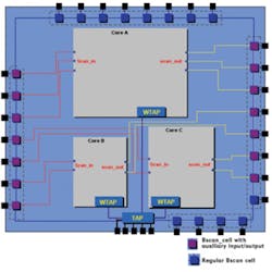
Each core using this hybrid test methodology flow has a 1500 IEEE interface also referred to as wrapper test access port (WTAP). This interface connects to the top-level TAP once the core is integrated in a chip. By loading the WTAP with the appropriate operation code, the core mode may be chosen.
Figure 2. Top-Level Integration
Each core has dedicated scan I/Os.
Because the WTAP may be loaded in this manner and the LBIST does not require external stimulus to run, multiple core built-in self-tests may be started in parallel. This maneuver is not always possible using ATPG because it needs external data routed through I/O. If all cores have dedicated ATPG scan I/Os on the chip level, it is possible to run all of them in parallel. However, if one I/O is shared among all cores, only one core may be run at a time.
Figure 2 is an illustration of a top-level integration in which cores A, B, and C have dedicated scan I/Os.
Some applicable test pattern configurations are outlined as follows:
Example 1. Full Parallel Test, Shortest Tester Time
- Test cores A, B, and C in parallel using LBIST test through the TAP
- Test cores A, B, and C in parallel using ATPG test through TAP and scan I/Os
Example 2. Mixed Parallel and Serial
- Test cores A and B in parallel using LBIST test and then test core C
- Test cores A, B, and C serially using ATPG
Example 3. Full Serial, Longest Tester Time
- Test cores A, B, and C serially using LBIST
- Test cores A, B, and C serially using ATPG
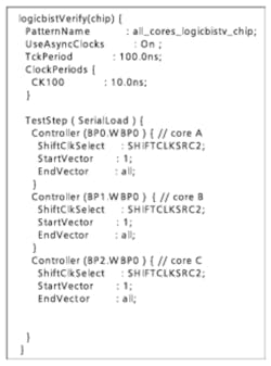
Figure 3. Configuration File for Parallel LBIST Patterns
These examples are possible without regenerating hardware or rerunning ATPG from the top level. This time-saving advantage occurs because cores A, B, and C were created through a flow that generates both LBIST patterns and ATPG patterns at core-level boundaries. When the cores are integrated in the top level, a tool reads the patterns previously generated at the core level and retargets them from the top level without requiring any new fault simulation or DRC. This process is referred to as pattern reuse.
If two cores have different scan chain lengths, the vector generator tool detects the different lengths and provides a script to patch the patterns of the core containing the shortest chains. For pattern generation, the vector generator tool automatically carries this out when the desired configuration is input.
Figure 3 is a configuration file that will help generate full parallel LBIST patterns for Example 1.
Implementation Flow
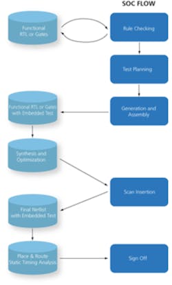
Implementation of the hybrid test methodology uses a Perl/Tcl–based flow on top of the pre-existing Mentor Graphics Tessent SOC flow, which will automatically insert and stitch at-speed LBIST IP and at-speed ATPG EDT IP. This method is a complete DFT flow.
It starts with DFT rule checking that can be run on gates or RTL. The next step is DFT planning, which consists of specifying the solutions to be implemented. DFT planning is followed by insertion of LBIST IP and deterministic ATPG IP.
Figure 4. Flow Used for the LBIST-
ATPG Hybrid Test Methodology
Next, gate-level scan insertion is completed. All necessary files and commands for implementation are automatically generated by the tool. These may include timing constraints for synthesis, place-and-route, static timing analysis tools, verification test benches, or test vectors in multiple formats. Figure 4 is a flow chart of the hybrid test methodology.
Cores were solely tested with LBIST and then only with ATPG. Next, the cores were tested using the combined LBIST and ATPG where the cores were running few LBIST patterns and targeting the remaining faults undetected by LBIST. The results of each of the tests where the LBIST and ATPG were used independently were then compared to the results of the combined test.
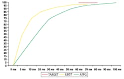
These experiments showed that LBIST alone reaches a high coverage in a short time because of a fast shift clock. However, LBIST could not attain the coverage required due to random resistant faults.
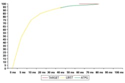
The experiments using only ATPG demonstrated that cores reach the coverage requested because ATPG is deterministic. On the other hand, ATPG had the longest test time compared to that of LBIST because of slow shift frequency. When using the combined LBIST and ATPG, results showed the same high coverage as ATPG independently running but with a shorter test time than when ATPG was run alone.
Figures 5 and 6 illustrate the results observed during the experiments running LBIST and ATPG alone compared to running LBIST and ATPG combined.
Figure 5. LBIST Full Pattern (yellow), ATPG Full Pattern (green), and Target (red)
Figure 6. LBIST Half of the Patterns (yellow), ATPG Top Off (green), and Target (red)
In conclusion, while the test-time reduction might vary from one block to another, adopting a hybrid methodology will help optimize your DFT solution and reduce your test cost with no impact on test quality. An extrapolation of this general observation also can provide a more concrete understanding of the advantages of using a hybrid methodology.
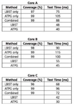
Table 1. Comparison of Fault Coverage and Test Time Results for Each Methodology
Assuming we have run the experiments on cores A, B, and C, the quantitative results in Table 1 would most likely occur.
Upon analysis of the results, it is apparent that LBIST alone cannot be used to sign off this chip because it does not achieve the required coverage of 99%. The remaining choices for sign off would be ATPG alone or the combined LBIST-ATPG. The overall test time will determine whether ATPG alone or combined LBIST-ATPG should be selected to test the chip.
Compare and calculate the test time for Example 3 using the top-level configurations presented in Table 1. All cores were run in serial. To calculate final test time for the chip for this configuration, find the sum of the test times of all cores. For ATPG only, 105 + 115 + 96 = 316 ms. For the combined method, 88 + 100 + 72 = 260 ms.
Analyzing the difference in final test times, a test-time economy of 56 ms is observed. This is a 17% test-time reduction without a loss of test quality. The combined LBIST–ATPG solution provides optimal results. Using the hybrid methodology, a DFT engineer can meet his or her requirements with more flexibility and automation as well as achieve optimal test time for the best test quality.
About the Author
Amer Guettaf is a senior field application engineer at Mentor Graphics specializing in design for test tools. Mentor Graphics, 46871 Bayside Parkway, Fremont, CA, 510-354-5891, [email protected]
