A great deal of EMC testing focuses on radiated high-frequency effects. Antennas, TEM and GTEM cells, shielded rooms, anechoic chambers, and OATS all have their place. However, conducted EMI also must fall within prescribed limits.
EUT-generated power line noise is of particular interest because it easily can propagate to other equipment. So, how do you safely measure noise on the power line in a consistent way that will allow before/after comparison as design changes are made?
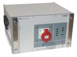
Courtesy of Rohde & Schwarz
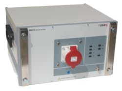
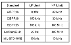
Two devices typically are used: a line impedance stabilizing network (LISN) (Figure 1) up to 30 MHz and a ferrite absorbing clamp from 30 MHz to 1 GHz. These ranges are commonly specified, but different applications and standards require other LISN ranges as shown in Table 1.
Data Source: Laplace Instruments LISN Datasheet
You may not have a LISN or ferrite absorbing clamp, but they can be rented and, being fairly straightforward devices, are relatively inexpensive. And, you don’t need a shielded room or anechoic chamber for conducted EMI tests. Consequently, it can be simpler to run accurate precompliance conducted EMI tests than for radiated emissions.
LISNs Under the Hood
The purpose of a LISN is to create a repeatable, stable electrical environment. It does this by rejecting noise while at the same time providing a defined impedance for measuring instruments. The LISN is inserted between the mains and the actual power connection to the EUT—one LISN channel per phase connection and neutral. Each EUT measurement channel output is separately available and can be connected to a 50-Ω instrument input.
To ensure that each line is loaded with the same impedance, some manufacturers suggest attaching a separate 50-Ω load to those LISN channels that are not connected to the measuring instrument. A LISN only presents its characteristic impedance when a 50-Ω load or instrument is attached.
Several variables influence the setup details most appropriate for a given EUT, but one of the most important considerations is grounding. Low-frequency noise must be filtered, so the amount of capacitance to ground is large. This can be a problem because very good grounding is required to handle the high currents. One consequence is that a LISN cannot be driven via a ground-fault interrupter although an isolation transformer can be used.
The measurement channels are single-ended, which emphasizes the need for a good RF ground connection as well as consistent LISN positioning. EMC test specifications call for a large metal plate to be used as the ground reference. It’s advisable to bolt the LISN to the plate to guarantee operator safety as well as ensure measurement repeatability.
To minimize high-frequency effects, mains wiring would be treated like communications cabling in which the signal and its return path are twisted together. To a very large degree, a twisted pair is much less susceptible to interference such as crosstalk because an aggressor field equally affects both wires, again canceling.
However, mains wiring is not twisted within an EUT so the live and neutral power cable wires can and generally do carry different noise signals. When a clamp-style current transformer is attached to the mains cable, it actually measures the common-mode interference signal because of the close proximity of the live and neutral wires. This is not the case with a LISN, which treats each phase and neutral as completely separate single-ended signal sources.
The Basics
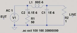
Figure 2 shows the equivalent circuit of a typical 50-Ω, 50-μH LISN as defined in CISPR 16-1-2, 2006 and simulated in Linear Technologies’ LTspice IV. The 1-Ω resistor at the line end simulates the actual line impedance but only has an effect at very low frequencies.
Although it’s easy to simulate the circuit behavior using any resistance value, in practice, impedance is measured with the mains end of the LISN either open circuit or shorted. The impedance magnitude at higher frequencies is largely unaffected by either choice. However, the low-frequency characteristic and phase are affected.
If the LISN is measured with the mains input open circuited, the so-called “V” plot results in which the impedance magnitude decreases from a very high value at DC, becomes a minimum around 9 kHz, and then increases toward 50 Ω—the plot looks like a V. If the mains input is shorted, the impedance magnitude simply rises from zero as shown in Figure 3. Shorting the mains input gives the characteristic phase curve also shown in the figure but has the disadvantage of effectively bypassing the 1E-6 capacitor in a 50-Ω, 50-μH LISN and the more extensive filter stage in a 50-Ω, 50-μH+5-Ω LISN.
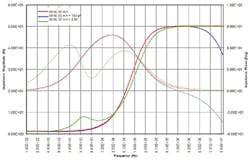
Figure 4 corresponds to an alternative LISN circuit, 50-Ω, 50-μH+5-Ω , with a 9-kHz lower frequency. According to a Fischer Custom Communications datasheet, this design originated with German VDE conducted emissions testing. The impedance magnitude and phase are shown as seen from the EUT. The curves have been slightly offset so each is visible even if, in reality, they are largely coincident. The interesting factor is the significant effect an additional shunt 100-pF capacitance has at high frequencies.
Because these LISN circuits most often are used at frequencies higher than 9 kHz or 150 kHz, the actual line impedance has very little effect other than on phase. To explore this dependency, the 1-Ω resistance was varied a great deal during simulation but the change at higher frequencies was small. As would be expected, at very low frequencies where impedances are low for the series inductance(s) and high for the shunt capacitances, the EUT sees the nominal line impedance, whatever it is. However, above the 9-kHz or 150-kHz lower frequency limit, the LISN obviously achieves the objective of stabilizing the line impedance.
Details, Details, Details
The circuits and simulation results have been simplified to clearly show how a LISN is intended to work. Several details taken from the Thurlby Thandar Instruments instruction manual for the company’s Model 1600 LISN demonstrate how a practical design met safety and high-frequency performance requirements. Although this is an older design, the considerations are relevant because the various standards organizations continue to require similar performance from a LISN.1
The LISN 1600 is a 50-Ω, 50-μH+5-Ω LISN, so both a 50-μH inductor and a 250-μH inductor are needed. The inductor closer to the EUT more directly affects the impedance seen by the EUT, so it was constructed of four 12.5-μH sections, each shunted by a separate 680-Ω damping resistor to control parasitic resonances above 20 MHz.
The 250-μH inductor has a ferrite core in comparison to the other inductor’s air core. An air core is preferred for lower inductance coils because it can’t saturate. On the other hand, a suitable ferrite core for a larger value inductor makes possible a much smaller physical size. This, too, is important because a very large coil would have more stray capacitance than a compact one. Also a much greater length of wire could increase resistive losses.
LISNs may have from one to four circuits in the same chassis. For automotive applications with long wires, two channels are required, one for the power line and one for the ground return. For very high current applications, CISPR 25 specifies a 50-Ω, 5-Ω H configuration.
A consequence of the high currents that a LISN carries is a relatively large amount of stored energy in the inductors. Switching the EUT on/off causes transient voltages that can damage measuring instruments. Even if the EUT power isn’t switched, damaging transients may exist on the mains anyway. For both reasons, The LISN 1600 has a 90-V gas tube across the instrument port with a 2.2-Ω nonflammable fusible resistance in series.
In addition, this LISN and many others provide a combination attenuator and voltage limiter. Some manufacturers supply the transient limiter as a separate device that’s inserted in the BNC coaxial cable to the measuring instrument. The mains environment is not without the occasional large transient, and some of these might damage a sensitive instrument such as a spectrum analyzer connected to the measurement port.
Clipping is a good way to deal with transients while allowing high sensitivity. Nevertheless, clipping circuits are not perfect, and the designers of the Model 1600 LISN determined that the diodes in the transient limiting circuit should be back-biased to reduce their effect on frequency response during normal operation. Lithium batteries are included to do this. Because only a very small reverse leakage current is supplied, the batteries have a 10-year expected lifetime.
An artificial hand is included with many LISNs. As described in Hameg Instruments’ HM6050-2 LISN manual: “This feature simulates the influence of the human hand. When performing EMC measurements for devices which are held in hand during use…the artificial hand simulates the influence of the human hand on the behavior of the equipment.”2
Finally, LISNs may be configurable to suit the requirements of different standards. For example, the Thurlby Thandar Model 1600 has a switchable 150-kHz highpass filter in the measurement path. When it is switched in, the noise frequencies below 150 kHz are greatly attenuated, further protecting a sensitive instrument.
LISNs are available from a number of EMC test companies including Com-Power, ETS-Lindgren, Fischer Custom Communications, Hameg Instruments, Kyoritsu, Laplace Instruments, Teseq, PMM NARDA, Rohde & Schwarz, Schwarzbeck Mess, Solar Electronics, and Thurlby Thandar.
Ferrite Clamps Under the Hood
When a conductor passes through or is wrapped around a piece of soft ferrite material, the ferrite’s high permeability causes an increase in the effective inductance of the conductor. However, ferrites have a complex permeability comprising both a purely inductive part μ’ as well as a lossy part μ”. Rather than simply shunting currents to ground as a LISN does, a ferrite clamp actually dissipates RF energy within the ferrite material.
Many materials are available with higher or lower permeabilities and covering different frequency ranges. Fair-Rite type 61 is a NiZn ferrite effective from about 20 MHz to beyond 500 MHz. At lower frequencies, MnZn types 73 and 31 are better suited.
Some materials are very susceptible to the magnetic offset caused by a DC bias. Also, ferrite impedance generally reduces with increasing temperature. For Fair-Rite type 61 material, this is a relatively small effect of about 0.15%/°C. It’s about three times larger in the higher permeability, lower frequency materials such as type 44.
In a current clamp, ferrite rings are used for three purposes. They form the core of a current transformer, provide inductance to reduce the level of RF passing from the EUT to the mains connection, and dissipate RF energy. The current transformer is placed closest to the EUT to sense the EMI level before it is affected by the remaining ferrite rings. After the current transformer, there are two sets of rings: one attenuates any pickup on the measurement path from the transformer, and the other filters the EUT EMI before it reaches the mains.
Courtesy of Rhode & Schwarz
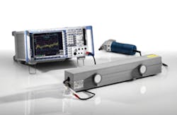
The current transformer and absorber clamp (Figure 5) fit around the entire mains cable, so the fields caused by the line and neutral currents largely cancel each other, leaving the transformer to measure the remainder. According to a Rohde & Schwarz datasheet, the EMI receiver reading in μV is equivalent to the emitted power level in pW plus a correction factor. Nominally, this is 17 dB but does vary with frequency so a table of correction factors should be used to get the most accurate results.
The datasheet explains that, because there is no matching between the EUT and the cable or between the cable and the absorber, the clamp must be slid among the cable to find the maximum noise current at each frequency. Interestingly, because both the line and neutral wires pass through the clamp, large DC or AC currents are accommodated. For the Rohde & Schwarz MDS-21 Absorbing Clamp, peak AC or DC current is specified at 30 A.3
To promote repeatability, the mains lead should be stretched and held straight so that it doesn’t move as the clamp is adjusted along it. Some manufacturers sell a long narrow table with rails to guide their absorbing clamp. In addition, there are semi-automated positioning systems that are used with the clamps.
Ferrite absorbing clamp manufacturers include Com-Power, Kyoritsu, Laplace Instruments, Metrix Electromagnetics, Rohde & Schwarz, Schwarzbeck Mess, and Teseq.
Why It Matters
According to Mark Terrien, EMC business manager at Agilent Technologies, “One of the key drivers for EMC precompliance testing is the economic benefit it can bring to any company developing products with electronic content. Early precompliance testing provides a higher level of confidence that new designs will pass full compliance testing the first time, which eliminates costly redesign late in the development cycle and a delayed market introduction.”
Terrien also described additional advantages of using a comprehensive precompliance test program with closely integrated hardware and software elements. Test automation, the choice of a receiver or a spectrum analyzer, and the availability of application-specific measurements are a few of the considerations you need to address to enhance your conducted EMI test capabilities.
References
1. LISN 1600 Line Impedance Stabilisation Network Instruction Manual, Thurlby Thandar Instruments.
2. Line Impedance Stabilization Network HM6050-2 Operators Manual, Hameg Instruments.
3. R&S® MDS-21 Absorbing Clamp, R&S EZ-24 Ferrite Clamp, Rohde & Schwarz, Datasheet.
