Failure to sufficiently cool an electronic component will lead to overheating, which can reduce its lifespan or even permanently damage the product’s internal system.
Selecting a cooling method for electronics generally comes down to four main options: natural convection, forced convection, fluid phase change, and liquid cooling. The right choice depends on identifying the electronic system needs and conditions in which it will operate.
Liquid cooling is often used for high-powered electronics, including PCs and transistors such as insulated-gate bipolar transistors (IGBTs), electric motors, and other systems where forced air isn’t sufficient to keep components cool and functioning at full capacity. The liquid used to cool these devices can be water, deionized water, glycol, dielectric fluids (e.g., fluorocarbons), and PAO.
The main benefits of liquid cooling are:
A high level of efficiency, sustaining low temperatures over time
Liquid cooling, most often using water, is much more efficient than air. Water has better heat-transfer capabilities and, for an identical flow rate and temperature limit, can carry more energy. Moreover, a liquid-cooling system keeps the temperature down at all times unlike air-based systems. In the latter, a fan starts to operate when components are already overheated, removing the excess heat rather than anticipating the issue.
Requires less space than air-cooled systems
Typical liquid-cooling systems include thin tubes that don’t occupy much space. For air-cooling systems, however, more space is needed to accommodate multiple fans.
Low noise
In a traditional cooling system, fans generate noise. A water-cooling system usually requires only one fan, which has the role of circulating the air. Because the water does most of the cooling work, noise will be kept to a minimum.
Role of Engineering Simulation to Validate a Cooling System
Engineering simulation, or computer-aided engineering (CAE), is used for complex virtual testing through numerical simulation. CAE enables the analysis of a design under different conditions early in the development process. The technology is used in iterative design processes and reduces the number of physical prototypes required to investigate a design.
In the following case study, four high-powered IGBT modules are simulated.
Case Study: Simulation of Water-Cooling IGBTs
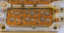
IGBTs are useful in high-load applications such as switched-mode power supplies, traction motor control, and induction heating (Fig. 1) .
The liquid-cooling simulation evaluates consumed and removed energy, junction temperatures, and heat path. Ultimately, the goal is to find out how the heat travels from the sources within the system and around the components to the exit point. Particular areas of interest are those where that incur resistance and temperature gradients are heightened. Once the information is acquired from the simulation results, design modifications can then be made for optimization.
The simulation type selected for this project is conjugate heat transfer (CHT). This is based on a thermal solver that computes velocities, pressure, temperatures, and other characteristics in both solid and fluid parts. CHT analysis is considered the most effective simulation type in electronics cooling applications.
CAD Model and Mesh
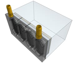
The CAD model used includes a water-cooling block, surrounding air, and an internal water channel. This design was directly imported onto the SimScale cloud-based CAE platform (Fig. 2).
Once the CAD was uploaded, a mesh was created using an automatic hex-dominant algorithm with five inflated layers on no-slip surfaces and moderate refinement.
Boundary Conditions for CHT Analysis
Boundary conditions for the analysis featured a velocity inlet and a pressure outlet for the water-cooling block. The velocity inlet tells the CAE software how much flow is coming into the water block. The inlet and outlet allowed for natural air convection to occur within the system. The pressure outlet represents the fluid exit where the temperature was defined.
Heat Source and Thermal Properties
The project dictated that each silicon IGBT, with a thermal interface, water block, and brass connectors, dissipated 368 W of energy. The heat generation was modeled as a volumetric heat source, and the materials were given standard values for thermal conductivity and specific heat capacities for each material, silicon, paste, aluminum, and brass. Evaluating the Liquid-Cooled Electronic Design
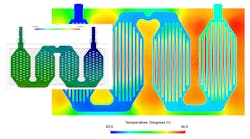
Analyzing the temperature distribution, it could be seen that the design allowed for uneven cooling, large temperature gradients, and unacceptable overall temperatures. The temperature gradient revealed that the biggest thermal resistances were due to conductivity within the thermal interface (Fig. 3).
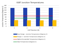
The IGBTs generated 1472 W of heat. The water-cooling system removed 92.6% of the heat and natural convection covered the remaining 7.4%. The maximum temperature of an IGBT should be around 32°C (90°F) to avoid damage through overheating. To increase the system’s longevity, a temperature below 21°C (70°F) is required. The first design revealed that the junction temperatures were too high (Fig. 4).
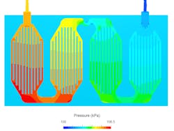
In addition, the CHT analysis results showed that the flow channel produced significant pressure losses due to the design’s sharp edges and contractions (Fig. 5).
Optimizing the Liquid-Cooled Electronic Design
As seen in the simulation results, the initial design of the electronic system would have experienced overheating. The reason is that due to the low conductivity of phase-change material (PCM) in the interface, the heat flow faced too much resistance around the component.
A simple design modification would be to reduce the thickness or improve the grade of the PCM altogether. Also, to reduce pressure losses and increase heat-transfer rates, it’s recommended to change the cooling block cavity design from channels to pins, enlarge contractions, and reduce the number of sharp edges or add fillets.
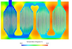
These changes were subsequently made to the liquid-cooled electronic design, and the CHT analysis was rerun. The final results showed significant improvements (Fig. 6).
Conclusion
Liquid-cooling systems have proven to be very effective in preventing electronics from overheating. Using the right system and placement, however, requires additional effort to ensure the best results possible over time. Testing designs with engineering simulation often makes the difference in this regard, allowing for quick optimization and design iteration.
In the case study described here, after the resistance areas were pinpointed and amended, the IGBTs’ internal temperatures were brought down to acceptable levels at the expense of PCM volume. Still, even more improvements are possible with an in-depth understanding of heat transfer. In addition, pressure loss was reduced and, as a result, energy on pumping the water decreased by approximately 50%.
Arnaud Girin is Technical Marketing Specialist at SimScale.
