To describe parts of embedded systems, designers will frequently use state machines, and that often means leveraging modeling tools like UML. These models are sometimes part of the certification process for safety-related applications. Turning these models into code can be challenging, especially if one needs to keep the model in sync with the code.
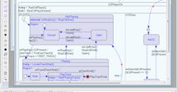
IAR’s Visual State (Fig. 1) allows designers to graphically construct state-machine models using the Visual State Designer. The hierarchical IAR models are compatible with the UML standard.
1. IAR’s Visual State allows designers to graphically create state machines and then turn models into C, C++, C#, or Java code.
Models can then be turned into C, C++, C#, or Java source code using the Visual State Coder tool. C# and Java are new additions. Changes made to the model can be easily turned into source code, allowing an application to be created from the latest model.
Visual State would be useful just for its ability to create source code, but it includes other handy features. The Validator, a state-machine simulation tool, allows a model to be tested regardless of what code will eventually be generated. The Verificator tool provides formal system verification. It can check for errors like state dead ends, ambiguous assignments, and unused elements.
For example, the Documenter tool is used to generate documentation reports in HTML or RTF formats. It correlates information from the Validator, Verificator, and Coder tools.
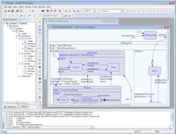
Visual State will work with any toolset since it generates source code, but it’s integrated with IAR’s own Embedded Workbench IDE (Fig. 2). A similar workflow would be used with any other toolset. The advantage of using IAR’s IDE comes when debugging and application. It supports state-machine breakpoints.
2. Visual State is integrated with IAR Embedded Workbench IDE.
IAR’s IDE also supports MISRA C/C++ compliance. Visual State includes an option to support the standard, addressing details such as avoiding embedding assignments in subexpressions.
About the Author
William G. Wong
Senior Content Director - Electronic Design and Microwaves & RF
I am Editor of Electronic Design focusing on embedded, software, and systems. As Senior Content Director, I also manage Microwaves & RF and I work with a great team of editors to provide engineers, programmers, developers and technical managers with interesting and useful articles and videos on a regular basis. Check out our free newsletters to see the latest content.
You can send press releases for new products for possible coverage on the website. I am also interested in receiving contributed articles for publishing on our website. Use our template and send to me along with a signed release form.
Check out my blog, AltEmbedded on Electronic Design, as well as his latest articles on this site that are listed below.
You can visit my social media via these links:
- AltEmbedded on Electronic Design
- Bill Wong on Facebook
- @AltEmbedded on Twitter
- Bill Wong on LinkedIn
I earned a Bachelor of Electrical Engineering at the Georgia Institute of Technology and a Masters in Computer Science from Rutgers University. I still do a bit of programming using everything from C and C++ to Rust and Ada/SPARK. I do a bit of PHP programming for Drupal websites. I have posted a few Drupal modules.
I still get a hand on software and electronic hardware. Some of this can be found on our Kit Close-Up video series. You can also see me on many of our TechXchange Talk videos. I am interested in a range of projects from robotics to artificial intelligence.


