This article appeared in Laser Focus World and has been published here with permission.
One size does not fit all in the ever-expanding world of fiber-optic communications. Step-index single-mode fibers conforming to the International Telecommunications Union G.652 specifications are sometimes called “standard single mode” because they have been widely used for decades. Yet G.652 fibers have evolved to changing needs, other single-mode fibers have been developed for new uses, multimode fibers have found new niches, and more-exotic fibers have emerged.
Those variations reflect the advantages of customizing fibers for particular applications. Bend-resistant fibers are needed for indoor use in conduits. Shrinking fiber cladding allows higher fiber counts in cables. Low-water fibers allow inexpensive coarse wavelength-division multiplexing (WDM) in 20 nm steps between 1270 and 1610 nm. Ultra-low-loss fibers can stretch amplifier spacing. Multimode graded-index fibers can carry high data rates over short distances, cutting transmitter and receiver costs.
The following is a guide to important types of optical fibers and their uses in communications.
Graded-Index Multimode Fibers
First developed in the late 1960s to increase the bandwidth of large-core fibers, graded-index multimode fibers now are used mainly for short data links. LED sources were used in the past, but now most data links are at speeds that require mass-produced vertical-cavity surface-emitting lasers (VCSELs) emitting at 800 to 960 nm. Most graded-index fibers have 50 μm, but some with 62.5 μm cores are still used. The table lists performance of standard multimode fibers.
In practice, multimode data links are used only to about 550 m, with single-mode fiber used over longer distances. Although multimode fiber has lower loss in the 1310 nm band than at shorter wavelengths, inexpensive VCSELs are only mass-produced in the short-wavelength band. OM3 and newer standards use VCSELs supporting data transmission rates of multiple gigabits per second.2
The OM5 standard provides for short wavelength-division multiplexing (SWDM) of 25 Gbit/s at two or four wavelengths at 850 to 953 nm to transmit at rates to 100 Gbit/s duplex. In January 2020, an IEEE task force approved the IEEE P802.3cm 400 Gbit/s over Multimode Fiber standard, which splits 400 Gbit/s signals among four or eight fibers spanning up to 100 or 150 m.3 Major applications are within large data centers and on short high-speed links in 5G networks.
Reusing Legacy Fibers
Installed legacy multimode fibers in data centers can be repurposed to transmit a single-mode signal at rates higher than those listed in the table. Cailabs (Rennes, France) has developed optics that couple up to 99.5% of a single-mode input into one of the fiber’s many modes. They report transmitting 10 Gbit/s up to a kilometer, and are testing rates to 100 Gbit/s.4
Legacy G.652 single-mode fiber installed two decades ago that remains dark or underused requires only minimal treatment before it can be lighted up and used. Thanks to digital signal processing and coherent optical transmission, G.652 fiber originally installed to transmit 10 Gbit/s on one or a few wavelengths can carry coherent 100 Gbit/s signals on up to 100 wavelengths without the need to splice different types of fiber in the proper arrangement to manage chromatic dispersion. That brings new life to legacy fibers and can save carriers the hefty costs of installing new cables, which can cost up to $500,000 in urban areas.
Single-mode fiber standards
The first version of ITU’s G.652 single-mode standard was drafted in 1984 when fiber communications was limited to 1310 nm, where chromatic dispersion is essentially zero. It called for mode field diameters of 8.6 to 9.5 µm, cutoff wavelength no more than 1260 nm, and attenuation no more than 0.5 dB/km at 1310 nm and 0.4 dB/km at 1550 nm.5 The development of erbium-doped fiber amplifiers (EDFAs) shifted most transmission to the 1550 nm window, but G.652 fiber remains in wide use, and the most-notable changes in the current G.652.D version are reducing loss limits to 0.4 dB/km at 1310 to 1625 nm and to 0.30 dB/km from 1530 to 1565 nm.6
Other new standards followed as fiber transmission evolved. Development of fiber with zero dispersion shifted to 1550 nm stimulated development of the G.653 standard. Adopted in 1988, the original version called for core diameter of 7.8 to 8.5 µm, zero chromatic dispersion between 1500 and 1600 nm, and maximum dispersion of 3.5 ps/(nm-km).7 Some zero-dispersion fiber remains in use, but severe four-wave mixing noise in the 1550 nm erbium band makes WDM impractical, except with amplifiers in the 1570 to 1625 nm L-band.8
The ITU G.654 standard was developed for another largely abandoned technology: submarine cables with zero dispersion near 1300 nm and the single-mode cutoff shifted to wavelengths as long as 1530 nm. Recent changes reduced maximum loss at 1530 to 1612 nm to 0.25 dB/km so it could be used for L-band transmission in dispersion-managed submarine cables.9
Development of WDM and dispersion management also led to the ITU G.655 standard for nonzero-dispersion-shifted single-mode fiber in 1996.10 That provides for chromatic dispersion high enough to prevent nonlinear crosstalk between closely spaced optical channels, but low enough to allow dispersion compensation by mixing fibers with different dispersion. Maximum single-mode cutoff was 1450 nm, with separate formulas for minimum and maximum chromatic dispersion that specified values between 1460 and 1550 nm and between 1550 and 1625 nm to allow dispersion compensation by splicing lengths of fibers with different dispersion.11
Another dispersion-driven standard is G.656, offered in 2004 as a single-mode fiber with low dispersion from 1460 to 1625 nm for widely separated WDM systems where four-wave mixing was not expected to be a serious issue.12 Later, it was modified for use in Raman optical amplification.13
Coherent optical transmission uses digital signal processing for forward error correction, which avoids the need for dispersion management and largely eliminates the need for standards that tightly specify dispersion.
Bending-Loss-Insensitive Fibers
Bend loss can be an important issue when fibers are installed in tight spaces both in access and in transport parts of the network, so ITU developed the G.657 standard that defines bend resistance for two fiber categories. Category A covers G.652-type fibers used in transport and access networks, which may be bent to a radius of 10 or 7.5 mm. Category B covers fibers in the access network that may not conform with G.652 and have low loss when bent to a radius of 7.5 or 5 mm.14
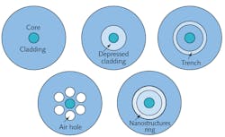
Bend losses occur where single-mode fibers encounter bends or tight packing, such as inside cabinets, cable ducts, risers, and partitions. One approach to limiting loss is to reduce the mode-field diameter to improve light confinement. Another is embedding a layer of glass with lower refractive index either as a depressed inner cladding adjacent to the core, or as a “trench” within the cladding. Other alternatives include embedding subwavelength holes or nanostructures in the fiber core. Figure 1 shows the placement of these structures; which option is best depends on application requirements. Bending loss also increases with wavelength being transmitted.15
Reduced-Thickness Fibers
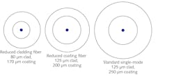
Reducing the thickness of a fiber allows fibers to be squeezed into smaller volumes and bent to a tighter radius without triggering the formation of tiny cracks that can lead to fiber breakage. It also allows more fibers to fit into a cable. There are two options: reducing the cladding and the protective coating that overlays it, or just reducing the protective coating (Fig. 2).
Standard fibers have an outer diameter of 125 µm, which is thick compared to the 10 µm core of single-mode fiber. It’s possible to reduce the cladding diameter to 80 µm, which reduces the glass volume of the fiber by a factor of 2.4. A reduced cladding fiber with a plastic coating has an outer diameter of about 170 µm, compared to 250 µm for a normal coated fiber.
Alternatively, the thickness of the coating applied to a standard 125 µm cladding can be reduced so the coated fiber’s diameter is only 200 µm, rather than the usual 250 µm.
Low-Water Fibers
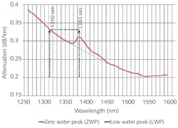
Standard fiber fabrication leaves traces of hydrogen, which bonds with oxygen in fused-silica fiber to hydroxyl groups that absorb between 1360 and 1460 nm with a strong peak at 1383 nm (Fig. 3). This band could be ignored when fiber systems operated only in the 1310 and 1550 nm bands, but became a problem for inexpensive coarse WDM at 20 nm spacing between 1270 and 1610 nm.
Processes have been developed to reduce hydrogen (often called “water”) in fibers to two levels. “Low-water” fibers typically have loss at the 1383 nm peak that is no higher than the loss at 1310 nm, which typically is below 0.34 dB/km. The current versions of the G.652.D and G.657 standards both specify that fiber loss should be no more than 0.40 dB/km between 1310 and 1625 nm, which is met by low-water fibers. The standards also call for loss at the 1383 nm peak to remain below 0.4 dB/km, even after aging.
Zero-water fibers further reduce OH absorption so that the 1383 nm peak is essentially gone, with attenuation below 0.27 and 0.31 dB/km. Attaining that low loss requires further processing with deuterium, the heavy hydrogen-2 isotope, to deter light hydrogen from bonding to oxygen in the glass, maintaining the low absorption.16 Figure 3 compares these fibers with each other and with standard G.652 fiber.
Other Special Features in Single-Mode Fiber
Some communications fibers offer features that optimize them for particular cases, such as stretching amplifier spacing or spanning very long distances.
One such feature is expanding the effective mode area for single-mode fibers. Although the core diameter of G.652 is nominally 9 to 10 µm, the single mode it transmits spreads out in a Gaussian mode so that the effective mode area is a bit larger—about 80 nm2.17 If such a fiber is transmitting high power, nonlinear effects can build up in the regions close to transmitters or amplifiers where power is highest. Expanding the effective mode area reduces power density in the core, reducing nonlinear effects. Changing the core-cladding refractive-index difference can increase effective mode area above 100 µm2, but there are limits.
Large effective mode areas can be combined with very low attenuation. For example, both Corning (Corning, NY) and OFS Optics (Norcross, GA) offer single-mode fibers for submarine cables with effective mode areas of 125 and 150 µm2 and attenuation below 0.16 dB/km at 1550 nm.
Special fibers are also made for tasks such as terminating or coupling fibers in communications systems.
Microstructured and Hollow-Core Fibers
A new generation of fiber technology has emerged based on microstructured fibers with holes running along their lengths. They rely on photonic crystals, photonic bandgaps, or other structures to confine light, opening new possibilities.
Microstructured fibers have differences in the refractive index of the material created by varying densities of microstructures; these index differences guide or confine light. If the microstructure is small compared to the wavelength transmitted by the fiber, holes it contains reduce the average refractive index of the holey material, so it can act as a low-index cladding guiding light through a solid or holey core.
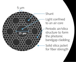
Photonic-crystal fibers create a photonic bandgap effect that blocks transmission of light at certain wavelengths through certain regions. This phenomenon can be used to confine light of certain wavelengths inside a core with a large effective area (Fig. 4), described by OFS Optics in the October 2020 issue of Laser Focus World. The latticework structure acts as an inner cladding. The six hexagonal cells labeled “shunts” surround the 25 µm core to divert higher order modes out of the large 25 µm core, leaving it effectively single-mode.18
Although a photonic-bandgap fiber has higher loss than a traditional solid-core fiber, its hollow core can transport light at 300,000 km/s rather than the 200,000 km/s of solid-core fibers. The lead in time of the light in the hollow core gains 1.5 µs/km, and microseconds mean money for high-frequency traders who pay a premium for transmission through the special cables.
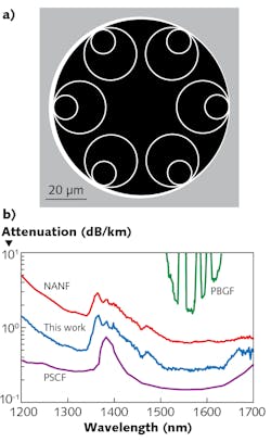
In 2020, Lumenisity (Romsey, England), a spinoff of the University of Southampton, introduced cabled fibers using a new type of hollow-core fiber based on nested antiresonant nodeless fiber (NANF) technology. Here, a solid cladding surrounds the hollow core, in which several nested pairs of cores run along the core-cladding boundary (Fig. 5). This approach allows low-loss transmission across a broader range of wavelengths than for photonic-bandgap fibers. At OFC 2020, Southampton researchers reported loss of only 0.28 dB/km at the 1550 nm minimum of solid-core fiber attenuation.
The Research Pipeline
Two other emerging types of solid-core fibers remain in the research pipeline.
Few-mode fibers have effective mode areas just slightly above the upper limit for single-mode operation, allowing them to carry only a few modes (compared to the hundreds or thousands in conventional multimode fibers). Researchers have shown that mode-division multiplexing can couple single-mode signals into and out of individual modes in few-mode fibers without significant crosstalk.
Multicore fibers have numerous separate light-guiding cores embedded inside their cladding, separated to prevent crosstalk. This allows core-division multiplexing, with each core transporting separate signals.
Both techniques have been demonstrated at high data rates, and experimenters have succeeded in making fibers that contain multiple cores with all cores carrying signals in multiple modes. The two techniques are classed as spatial-division multiplexing, along with the less-elegant approach of transmitting separate signals in separate fibers in the same cable or in parallel routes. Some form of spatial-division multiplexing lies in our future, but it remains to be determined which of the approaches will be most cost-efficient in telecommunications systems.19
References
1. See http://bit.ly/HechtFeb21-Ref1a and http://bit.ly/HechtFeb21-Ref1b.
2. See http://bit.ly/HechtFeb21-Ref2.
3. See http://bit.ly/HechtFeb21-Ref3.
4. See http://bit.ly/HechtFeb21-Ref4.
5. See http://bit.ly/HechtFeb21-Ref5.
6. See http://bit.ly/HechtFeb21-Ref6.
7. See http://bit.ly/HechtFeb21-Ref7.
8. O. Aso, M. Tadakuma, and S. Namiki, Furukawa Review, 1, 19 (Dec. 1999); http://bit.ly/HechtFeb21-Ref8.
9. See http://bit.ly/HechtFeb21-Ref9.
10. See http://bit.ly/HechtFeb21-Ref10.
11. S. Watanabe, T. Naito, and T. Chikama, IEEE Photonics Technol. Lett., 5, 1, 92–95 (Jan. 1993); doi:10.1109/68.185071.
12. See http://bit.ly/HechtFeb21-Ref12.
13. H. Masuda et al., OSA Technical Digest Series (CD), paper PDP20 (2007); http://bit.ly/HechtFeb21-Ref13.
14. See http://bit.ly/HechtFeb21-Ref14.
15. See http://bit.ly/HechtFeb21-Ref15.
16. See http://bit.ly/HechtFeb21-Ref16.
17. See http://bit.ly/HechtFeb21-Ref17.
18. D. Inniss, Laser Focus World, 56, 10, 40–41 (Oct. 2020); http://bit.ly/HechtFeb21-Ref18.
19. Í. Brasileiro, L. Costa, and A. Drummond, Opt. Switch. Netw., 38, 100584 (2020); http://bit.ly/HechtFeb21-Ref19.

