Making the Right Connections in Photovoltaic Systems
What you’ll learn:
- What do designers demand of connectors for today’s photovoltaic systems?
- Examples of the latest connectors for solar-panel installations.
Solar power is changing the world, but the photovoltaic (PV) transition is taking some time. As reported back in the Sept. 2018 issue of Electronic Design, fossil-fuel and nuclear energy are still the predominant sources of energy in today’s world, while large installations of renewable energy are growing. Coal continues to decline as a viable future energy source and nuclear energy has more or less peaked out, depending on plant age and location. Among the renewable energy alternatives, including wind and water power, PV energy generation continues to improve in terms of energy-conversion efficiency and market share.
Newer cell technologies like organic (carbon-based) and inorganic perovskites steadily push the envelope toward maximum theoretical PV efficiency. Tandem cells that can independently capture two different regions of solar spectrum using both silicon and perovskite technology continue to improve efficiencies.
The freely published and often updated graph from the National Renewable Energy Laboratory (NREL) has been of interest to PV watchers for decades (Fig. 1). It demonstrates the continuing rise in efficiency that shows both incremental improvements and the significant jumps enabled by new approaches.
PV cell efficiency is the percentage of power output (kW) per cell area (square meters) based on standard conditions of illumination, with a few other considerations like ambient temperature and the spectral content of the illumination modeled after natural sunlight.
We have witnessed over the past decade the development of very large and powerful solar farms in production around the world (Electronic Design, March 14, 2019) . These installations, as well as the many thousands of smaller ones in homes, businesses, or campus-size microgrid arrays, are successfully supplying real electricity. For local installations, in periods of peak sunlight, when the power exceeds local consumption needs, PV electricity can be fed back to the conventional grid, literally running the meter backwards.
Connector Requirements
Like any evolving technology, some practical problems continue to be addressed and solutions refined. Design goals for PV panel installation connectors must include:
- Ability to quickly string together individual panels with minimum labor time and effort.
- Keyed pairs of connectors to keep polarity foolproof and simple.
- Positive latching once installed to prevent unwanted disconnection.
- Minimal or no specialized tooling.
- Ability to accommodate different wire sizes.
- Safety approvals (UL, IEC).
- Materials must be compliant with global substance restrictions like EU RoHS and REACH.
- UV radiation resistant and water resistant (IP67).
- Low contact resistance to minimize losses.
Here we present example of how these design criteria were implemented and made available to the growing market.
First Connection
Making reliable connections between panels is the first step. In the past 10 or so years, several choices have been made available by different manufacturers. Historically, the crimping type of connectors such as the PV4 were mostly used for panel interconnection. More recently, the PV4 series has been upgraded to PV4-S—these male and female connectors are rated to 1500 V per UL6703 and are waterproof according to standard IP68 (1 m of water for 24 hours).
For system efficiency with low loss, these connectors feature low contact resistance (0.35 mΩ). Current ratings by UL depend on wire size, which can range from 15 A for 14 AWG (2.5 m2), to 20 A for 12 AWG (4.0 m2), and 30 A for 10 AWG (6.0 m2), all at 85°C.
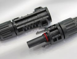
Figure 2 shows the pin and socket pair. Standard offerings include complete kits, contacts only, and housings only, in quantities from 100 to 2,000 pieces. Specifically, the 2270024-1 pin connector and 2270025-1 socket connector are RoHS and REACH compliant and contain no brominated or chlorinated flame retardants or PVC.
Wiring with Minimal Tools Required
The SOLARLOK 2.0 DC Plug connector system developed by TE Connectivity features insulation displacement connection (IDC) technology (Fig. 3). Both male and female ends incorporate the SOLARLOK 1,500-V PV4-S interface for versatility and compatibility with solar PV connectors equipped with a standard solar interface.
Internally, the IDC approach uses four rotatable blades providing both a cutting edge and contact surface. The blade shapes are designed to cut double insulated cable and provide robust conductor compression without cutting the strands. The intended benefit is low power loss through low contact resistance.
IDC connector assembly means no cable stripping is required. This is a significant advantage when multiple panels are being installed, potentially reducing overall cost and assembly time. The cable that’s cut to length is inserted and the connector halves closed. No cable stripping or custom tooling is required.
Outdoor connections are always a reliability concern. SOLARLOK 2.0 DC Plug connectors are gel-filled, which is a unique feature. The Powergel provided is a two-part mixture that’s used in a 1:1 mixing ratio; it cures in two hours at room temperature. Once applied and the IDC connector is closed, the gel seal is tacky to adhere to surfaces and provide a seal over a wide temperature range from −40 to +90°C. The gel is compatible with standard cable jacket materials and performs independently of cable jacket size.
SOLARLOK 2.0 connectors are also RoHS and REACH compliant as well as low halogen. They carry the CE mark and meet IEC 62852 and UL 6703 requirements.
Putting It All Together
With the panels cabled together, their outputs can then be combined for feeding to the load.
Commercially available junction boxes are available for this purpose. A charge controller is needed next to feed the battery bank. From there, an inverter changes the battery dc to the ac voltage used in the local power grid, 120 V ac in the U.S.
References
Levent Bas, “Types of Solar Connectors and Couplers,” CED Greentech website.
More product information is available at www.TE.com/SOLARLOK.


