Rotman-Lens Antenna System Harvests 28-GHz 5G Energy
What you'll learn:
- How did a Georgia Tech team overcome certain limitations to develop an antenna that harvest energy in the 28-GHz band?
- The key role played by the Rotman lens in making it all happen.
- Test results achieved by the lens-based rectenna.
With all the ongoing 5G activity, it makes sense that even non-5G applications would seek ways to leverage and harness some of its associated technological advances and energy (figuratively and literally). That’s what a team at the Georgia Institute of Technology (Georgia Tech) has done via an innovative antenna and power-harvester combination designed to effectively capture and rectify some ambient energy in the 28-GHz 5G band. This would be a good fit with many smaller-scale applications such as IoT devices, by reducing or possible even eliminating their need for batteries.
The idea of such an antenna (called a “rectenna”) isn’t new. However, making one that works and works well at 28 GHz is a challenge due to some difficult technical realities and tradeoffs. On one side, it’s desirable to have a larger, high-gain antenna to capture a meaningful amount of RF energy despite the high path loss at these higher frequencies, but such antennas have a narrow angular field of view.
While it’s possible to use a basic array of small antenna elements with each functioning as a rectenna and then combining their dc outputs, that obvious approach doesn’t increase the turn-on sensitivity (lowest turn-on power) of the overall rectenna system and thus its threshold of useful functioning.
To overcome the constraining tradeoff between rectenna angular coverage and turn-on sensitivity as well as other limitations, the team incorporated a unique version of a Rotman “lens” between the antennas and the rectifiers. This eponymous lens itself isn’t new: It was introduced by Walter Rotman in the 1960s and is one of the most common and cost-effective designs for beamforming networks (see References below).
The lens allows multiple antenna beams to be formed without the need for switches or phase shifters. In overly simplified terms, the beam ports are positioned such that constant phase shifts are achieved at the antenna ports with the antenna elements fed at phases that vary linearly across a row. As a result, it behaves just like a phased array. (One important property of this lens is that even though it has many attached 50-Ω ports, they’re isolated and thus don’t affect the loss—or noise figure—of adjacent beams.)
“We’ve solved the problem of only being able to look from one direction with a system that has a wide angle of coverage,” said senior researcher Aline Eid in the ATHENA lab at Georgia Tech’s School of Electrical and Computer Engineering, established to advance and develop novel technologies for electromagnetic, wireless, RF, millimeter-wave, and sub-terahertz applications.
Begin with a Subarray
The project team began the design with an antenna subarray. Multiple such subarrays, rectifiers, and dc combiners were then used to demonstrate the large angular coverage and turn-on sensitivity. Among the many data points, they showed a harvesting ability up to a distance of 2.83 meters in its current configuration, projected to reach about 6 μW of dc power at 180 meters with 75-dBm effective isotropically radiated power (EIRP). In addition, the system has a very low profile to conform to surfaces such as walls, bodies, vehicles, and other devices.
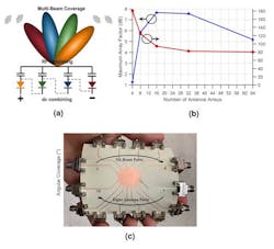
Based on their detailed analysis of the number and size of the subarray elements and available materials, they concluded that a subarray combination composed of eight antennas and six beam ports offered a nearly optimal compromise between a high array factor of 5.95 dB and a 120° total angular coverage, while maintaining a reasonable number of antennas and beam ports. The design was printed on a flexible copper-clad liquid-crystal-polymer (LCP) substrate (εr = 3.02) using an inkjet-printed masking technique followed by etching (Fig. 1).
The Overall Lens-Based System
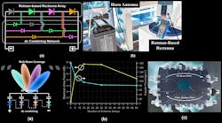
The overall system architecture (Fig. 2) has eight antenna subarrays attached to the Rotman lens from one side, facing six rectifiers at the opposite side where a dc serial combination is implemented using MACOM MA4E2038 Schottky barrier diodes.
The Rotman-based rectenna turns on well below −6 dBm/cm2, which the team says compares quite favorably to other devices in published literature. The output voltage of the rectenna also was measured over its operating frequency range with the system positioned at the same harvesting angle, at a range of 25 cm away from the source’s horn antenna and from 27.8 to 29.6 GHz.
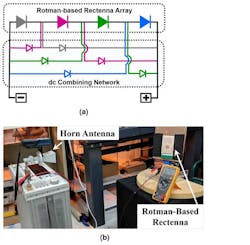
Toshiba 1SS384TE85LF bypass diodes were used in the dc-combiner design to create a low-resistance current path around all other rectifiers that received very low or close-to-zero RF power (Fig. 3). This topology is optimal when only one diode is turned on, which can be assumed if a single, dominant source of power irradiates this particular design from a given direction.
This simplified schematic shown has just four diodes. Different colors highlight the paths that the current will take for each case where an RF diode turns “ON” while the serially connected diodes are “OFF.” This dc combiner was fabricated on a flexible, 125-μm-thin polyimide Kapton substrate and connected to the Rotman lens-based rectenna through a series of single connectors to make the entire system fully flexible and bendable. The dc combiner uses a reduced number of bypass diodes and increases the angular coverage of the system by more than 30% compared to existing designs.
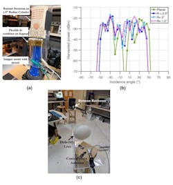
To verify performance under convex and concave flexing conditions, the lens-based rectenna was placed on cylinders with different curvatures at a distance of 70 cm from the transmitter sending 25 dBm of power at 28.5 GHz (Fig. 4). The voltage was collected using a 1-kΩ load for the planar and three bent conditions with respect to the source’s angle of incidence.
The graph shows excellent consistency and stability in the system’s scavenging and rectification abilities, even though several subsystems are exposed to warping and the pressures of bending: the antenna subarrays, the Rotman lens, and the rectifiers. There’s slight attenuation seen at the edges, but the system otherwise performs unimpeded by the bending. This property makes it a good fit for use with wearables, smartphones, and conformal 5G energy harvesters for IoT nodes.
Demonstration of the lens-based rectenna for longer-distance harvesting used a high-performance antenna system with a 19-dBi conical horn antenna and a 300-mm-diameter PTFE dielectric lens (for high directivity) providing an additional 10-dB gain. With a transmitted power of 25 dBm (and an associated EIRP of approximately 54 dBm) corresponding to an incident power density of approximately −6 dBm/cm2, the lens-based rectenna showed an extended range of 2.83 meters under open load conditions, with an output voltage around 10 mV. The researchers believe that this is the longest-ranging rectenna demonstration at millimeter-wave frequencies done to date.
The project was supported by the Air Force Research Laboratory and the Emerging Frontiers in Research and Innovation (EFRI) program of the National Science Foundation. Full details are in the three-author paper with the deceptively nondescript title “5G as a wireless power grid” published in Nature Scientific Reports. (Personal perspective: While the paper does have all of the desired details, data, and reference citations, I found it somewhat hard to follow; it needs better organization, layout, clarity of sentences, and story flow, along with much-shorter paragraphs.)
References
Microwaves & RF, “Rotman Lens’ Electronic Beam Steering Aims At 5G Signals”
W, Rotman and R.F. Turner, "Wide Angle Microwave Lens for Line Source Applications," IEEE Transactions on Antennas and Propagation, 11(6) pp. 623-632, 1963.
W. Rotman, U.S. Patent 3170158, “Multiple Beam Radar Antenna System”
Microwaves 101, “Rotman Lens”
