The Evolution of Polarization—Why Resolution is Now Too Simplistic a Metric
What you’ll learn:
- How do polarization technologies work?
- Advances in imaging technologies.
Imaging sensors have undergone many advances in the past two decades. At the heart of it all was enabling better pictures that led to better decisions being made more quickly.
The move to CMOS image sensors was a key to this evolution, making it possible for sensors to output digitally and automation/machine learning to be applied more easily. Similarly, the move to global-shutter CMOS image sensors removed artefacts from moving objects. And, of course, sensor manufacturers constantly strive to deliver increasing resolutions and optimize pixel count with sensitivity to provide the best quality image.
More recently, many advances have looked to capture what humans can’t see. For instance, last year saw the launch of shortwave IR sensors that also could capture the visible spectrum and output digitally. Another example of this trend is time-of-flight sensors, which add depth information to images and are being applied to a host of industrial and commercial applications. One of the most interesting new advances is the ability to bring polarization filters onto the sensor.
By doing this, we can detect otherwise invisible stresses and weaknesses in a product. And it eliminates glare that would otherwise hide defects in manufacturing and quality inspection as well as hinder detection and enforcement in intelligent-transport-systems (ITS) applications.
The Evolution of Using Polarization in Imaging Apps
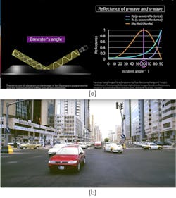
The use of polarization filters in imaging applications isn’t new. The traditional approach to minimize glare was to use a camera with a polarized filter on the lens. With the camera positioned at Brewster’s angle in relation to its subject (Fig. 1), it’s possible to eliminate the reflected glare to see through, for example, a driver’s windscreen.
However, this wasn’t a perfect situation, with the filter only able to filter light in a single plane. This meant multi-camera rigs, none of which can be in the same position as the other and therefore creating a perspective distortion. Or filters that can be switched at high speed, which results in delays—not ideal if you’re capturing vehicles or industrial manufacturing processes.
More recently, on-chip polarization filters have been developed. Sensors filter light using four directional polarizers and then apply this data to compile optimized images that remove glare.
In 2018, the first commercial image sensor with on-chip polarization was launched. It has since been adopted widely by a number of camera manufacturers.
How On-Chip Polarization Works
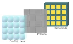
On-chip polarization uses a wire-grid layer positioned immediately above the photodiodes. The wire grid is set in four directional polarizers—0°, 90°, 45°, and 135°—and arranged in a 2x2 configuration (Fig. 2). Once light enters the sensor’s on-chip microlens, it’s filtered so that only polarized light reaches the sensor.
From this, the sensor creates four images that can be merged to give the clearest image. For example, it can confirm the driver in a speeding offense, or see through a pharmaceutical blister pack to check for damaged tablets.
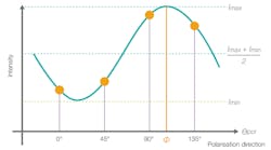
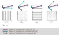
Data from the four polarization filters, and the differences in intensity between them, also can be used to calculate the angle of light entering the camera using Malus’s cosine-squared law (Fig. 3). It involves plotting the signal output from each pixel in the calculation unit against the transmission angle of each polarizer (qpol) angle and fitting a cosine function to calculate the angle (f) (Fig. 4).
This is particularly important in quality-control applications where a change in the reflection plane at a microscopic perspective might indicate an object has an otherwise invisible scratch or is under stress, both of which could lead to failure.
Increasing Resolution
The first generation of polarized sensors used a 2/3 type format outputting at 5.07 MP—four 1.25-MP images for each polarization direction. A second-generation 1/1.1 type sensor also was announced that increased the image resolution to 12.37 MP—four 3.09-MP images.
Applications
Initial applications have focused on those in electronics manufacturing, where glare can reduce the accuracy of pick-and-place machines, such as in pharmaceuticals, where it could prevent quality-control inspection being made through plastic pill packets. Or in ITS, it would hinder being able to see through the windscreen.
These applications aren’t surprising. Manufacturing recalls are potentially crippling for a company and any system that can prevent damaged products leaving the plant will prove crucial. Similarly, in ITS, the time and cost of prosecuting dangerous driving means dangerous behavior could go unpunished. To wit, although limited data is available, the state of Baden Württemberg reported that the difficulty of recognizing the driver from an evidence photo led to two-thirds of prosecutions stalling in such cases.
We’re starting to see the technology emerge in industries such as mobile-phone display production, where glass is under stress and any weakness will more quickly result in a cracked screen.
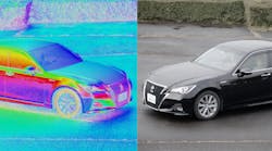
One of my favorite applications shows that science will often imitate nature. Several sea creatures have been shown to use polarized light vision to detect their prey in the murky depths, using it to get a 3D picture and render camouflage ineffective. And by using these sensors to calculate and color each surface reflection plane, it’s possible for a vision system to identify the object as a three-dimensional shape, increasing the confidence in component selection or object detection—even against a similarly colored background.
Conclusion
Imaging sensors have undergone many advances in the past two decades, with systems striving to improve the accuracy of decisions based on images, be it for manufacturing, ITS, agriculture, or autonomous vehicles and robots.
As such, resolution has been a key focus of those specifying and selling such systems. It’s not hard to understand why. Like the processor in a PC, it’s an easy-to-grasp metric that doesn’t rely on subtlety. I’ve even used it in the above to describe the advance of polarized sensor technologies.
However, many advances that improve the speed and accuracy of imaging systems aren’t down to improvements in resolution. Instead, they’re from additional data that new-generation sensors can provide. Hyperspectral information (from short-wave infrared, or SWIR, imagers) can detect damage in fruit and vegetables; distance information (from time-of-flight, or ToF) can be used to guide logistics robots and improve safety on building sites; and the information from polarization sensors can prevent imaging-system failure from glare and identify weaknesses in the manufacturing process.
The rise of such sensors that allow us to see more (rather than just zoom in more) means we need to find better ways of giving information to system developers.
We’ve so far been lucky that the industry is open to new ideas, with polarized, SWIR, and ToF all being well-adopted. However, the next breakthrough sensor might not fare so well if too many resiliently rely on such a simple metric when evaluating a camera.
