How Do You Counter the High-Radiation Environment of Space?
Members can download this article in PDF format.
What you'll learn:
- Main issues confronting designers when design orbit-based equipment.
- The types of radiation that can lead to "events" that damage equipment.
- How to mitigate the impact of these events.
- How to handle software errors.
It’s an understatement to say that launching equipment into space isn’t cheap. Even with costs dropping in recent years, the cost of a satellite and its launch can still be anywhere between $10 and $400 million. Indeed, a geomagnetic storm in February is estimated to have caused approximately $50 million of damage to SpaceX’s low-Earth-orbit (LEO) communication satellites. Weather-monitoring satellites cost approximately $290 million.
And that’s before maintenance costs, with component failure requiring either in-space repair or causing the entire system to be written off. In short, all equipment must incredibly reliable and be able to withstand the extreme environment.
There are essentially three key differences faced by chip and system engineers when creating orbit-based rather than ground-based equipment.
The first is temperature, with equipment needing to be protected from extreme (150°C) fluctuations and an operational level maintained. The second is the vacuum.
Collectively these create a different cooling effect than on the ground, relying solely on thermal radiation rather than air convection. This requires slightly different calculations for heat dissipation. It also creates issues with moisture, which gets into the package on the ground and then seeps out of the package once in orbit, potentially delaminating the package from the board. Thus, a separate qualification is required to make sure that you don't have trapped moisture in the package before launch.
These two issues are relatively straightforward to mitigate through packaging and insulation. The third (and arguably more challenging) difference encountered by electronic components in space is radiation.
Radiation Encountered
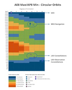
The magnetosphere of the Earth concentrates particles into two main belts (Fig. 1). The lower belts mostly consist of protons, and the upper belts being mostly electrons, with most of these particles coming from the sun via solar wind / solar flares. Any remaining particles come from cosmic radiation from other galaxies.
While it's difficult to replicate the full test environments on Earth—to generate some of these particles would require in the region of giga electron volts—these belts are at least very well understood and were being studied by NASA since the start of its space programs. Depending on the equipment’s orbit, it will pass through these belts at different rates.
Anything that's operating in a polar orbit, such as a spy satellite, will be crossing through the concentrated radiation belts on a regular basis and need protection from a higher radiation dose. Whereas LEO satellites operate at 1,000 to 1,500 km and thus undergo lower levels of radiation.
So, depending on these factors, a satellite can absorb between 1 and 10 kilorads per year. Therefore, we need to calculate the dose a satellite will receive during its lifetime.
Effect of Radiation
In addition to dose, we need to look at the types of radiation and the damage they cause.
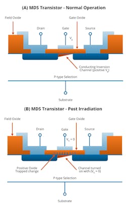
Let’s first look at ionizing radiation (non-ionizing radiation is discussed toward the end of the article), which can come from protons or electrons. These particles strike the gate oxide of the semiconductor and cause damage through a build-up of charged particles in the MOSFET gates (Fig. 2).
In a PMOS transistor, this increases the threshold voltage and makes it more difficult to turn on. Conversely, in an NMOS transistor, the opposite is true, making it turn on at a lower threshold.
And the probability of this happening is proportional to the size of the gate. Consequently, older process nodes tend to have a higher probability of radiation damage to the gate oxide.
In addition, in an analog design, you can get bandgap shifts, changes in bias current leakage side effects, and an increase in the 1/F noise.
Types of Events
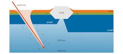
There are two possible outcomes following an impact: a non-destructive or destructive event (Fig. 3). A non-destructive event might be a single-event upset in a storage element, a soft error where the radiation causes a noise spike and changes a memory location from a zero to a one.
A destructive event might be a single-event gate rupture, which mostly affects power devices. Or, if the particle impact energy is high enough, it also can cause a single-event latch-up, which results in a device turning on permanently until a power cycle is undertaken. And depending on the device, this can be catastrophic.
Thus, you need to detect and protect the equipment against these events. We've looked at these single end events and their effects tend to come more from the heavier particles, creating electron hole pairs and a transient conduction path; flipping memory locations and flip-flops is a concern, too. And that tends to be how most of these things are tested: Placing a large memory on a device, radiating it, and then measuring the number of errors across the megabits of memory.
Latch-up is a separate test and you need to put in protections to detect power surges and read the ability to reset critical devices.
Mitigation Techniques
First is gate selection. For example, with a power transistor, which must not switch on by accident, it’s better to use PMOS than an NMOS.
In addition, because the probability increases with size, there’s some advantage in going to smaller process nodes, but that that does bring in other risks as well.
And there are specific design mitigation techniques such as avoiding gates with many inputs.
Beyond these basic steps, a host of other specific mitigation techniques target both single-event upsets and single-event latches.
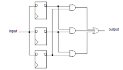
Noteworthy among these is the triple-redundancy flip-flop (Fig. 4). This (and its multiple variants) often has been used in the aerospace industry, as it offers the best possible protection against single-event upsets.
But there are disadvantages that prevent the triple-redundancy flip-flip from being used throughout the design: It's going to triple the size of your solution and increase power demands from the whole system. But they should be deployed in critical areas where you've got key decisions being made.
To avoid a glitch on a clock causing the same error to propagate through, it’s also possible to jitter or defer the clocks to each of the flip-flops so that they're all completely independent. The downside for this method is that it doubles the safe faults rate.
Finally, you could have a fully redundant system with separate microprocessors where the results are compared. And only when there's a majority of votes is the output allowed to be used to decide. Again, this is an expensive solution.
In short, the mitigation technique employed will depend on the criticality of the component and the likelihood of a destructive event affecting it.
Predicting and Fixing Software Errors
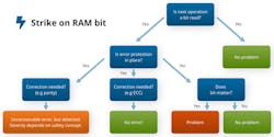
After an incoming particle strikes RAM, the problem depends on where the next step is read or write. If you're going to be reading that data, you've got a problem. And if the next operation is a write, then the error is going to be cleared. So how do you predict what's going to happen?
It's completely interdependent to the software operation of the system. And, of course, you can put in memory refresh strategies to try to keep your memory clean.
Taking this a few steps further, for some functions—where the data isn’t critical to the function—you can ignore it and carry on.
For more critical elements, you could deploy error correction code (ECC) to give you error protection, with the ECC built into the memory (Fig. 5). It should be stated that you will not always have enough correction parity to fix every error. However, even in this case, such an approach will still be able to detect an error, alerting you to a problem and preventing you from proceeding with certain actions or functions at critical stages.
Additional steps that can be taken include the implementation of cyclic redundancy checks into communication channels; or setting the state machines’ Hamming distance to be greater than 1, which will avoid accidental flipping into another state.
Beyond that, it’s possible to run software self-test procedures, as well as have the hardware check on the software and the software check on the hardware. Of course, there are external watchdogs, too, as we have in embedded systems. Finally, a remote-control-based internal clock monitor or safety clock can be recovered from a PC.
Coping with Non-Ionizing Radiation
As alluded to above, there are also effects from non-ionizing radiation. Displacement damage leads to more gradual effects, with bits of the silicone structure becoming damaged over time and leakage that causes decreased gain in bipolar transistors.
This effect has been documented in satellites, notably with CMOS imaging sensors becoming damaged over time. In this case, the component might need replacement at some point, or the use of larger devices to create spare pixels and extend the life of the satellite.
Again, a host of mitigation techniques can be deployed, including the incorporation of some form of redundancy or ECC into the system. On the analog side, it’s advisable to monitor the voltage and current carefully—if there's a latch-up, you can more easily detect it and shut things down quickly.
And silicon layout plays a crucial role. Here on Earth, there's always a push to put the metal tracks closer and closer together with each generation, with designs taking them to the absolute limits of what the technology can support. However, for electronics designed for use in space, it’s advisable to increase the separation of the critical node to give greater protection.
So, is Your Chip Space-Qualified?
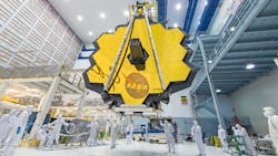
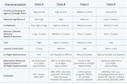
Can you use something off the shelf? It’s a little (lot) more difficult than that, and the answer, of course, is “it depends.” NASA has tried to define four classes: A,B,C, and D (Fig. 6). These depend on the mission and its lifetime. For example, the James Webb Space Telescope is Class A (see opening image).
Conclusion
The ionizing radiation that electronic components will undergo in space can cause significant damage if it’s not considered from the beginning of their design.
Several mitigation techniques can be deployed. However, cost and size limitations prevent them being used throughout a system. Thus, careful cost vs. risk analyses must be performed when developing the system as a whole.
*The opening image of the James Webb Space Telescope is credited to NASA/Desiree Stover.
About the Author
Paul Morris
VP of the RF and Communications Business Unit, EnSilica
Paul Morris is VP of the RF and Communications Business Unit at EnSilica. The company has developed a range of automotive, medical, and satellite ASICs, including Ka-band vehicle-to-satellite communications equipment for the European Space Agency.
