Three-Axis MEMS Accelerometers Transform IoT Machine Monitoring
Download this article in PDF format.
Quantifying the vibration of industrial machinery and using that information for condition monitoring (CM) has long been an ambitious goal, but also one with significant technical and implementation challenges. It’s usually done using accelerometers that sense motion and provide a corresponding signal for further analysis.
While that approach seems straightforward, the reality has been more much difficult until recently. Now, however, the availability of high-performance, multiaxis accelerometers based on MEMS technology has radically transformed and improved the situation in many ways.
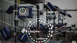
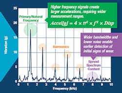
Why vibration? In a perfect world, there would be no vibrations from bearings, shafts, and other components of rotating machinery. These vibrations are due to unavoidable imperfections, balance issues, and slightly bent shafts and rotors, and aggravated by ongoing wear and use. Since the real world is certainly not perfect, different types and aspects vibration will reveal a great deal about present conditions, as well provide insight into worrisome trends and even impending failures of bearing, shafts, and machine tools (Fig. 1):
- For bearings, the initial signs of wear typically create high-frequency noise that requires wide-bandwidth, low-noise sensors for early detection of initial bearing wear, which is often due to the impacts created by small fragments of metal.
- For shafts and motor frames, subtle changes in alignment and balance that can adversely affect motor performance demand low-noise, extremely stable accelerometers.
- Finally, the increased vibration levels of machine tools during high-speed operations, such as milling or cutting, can damage critical materials and reduce precision. Such cases require wide-bandwidth, low-noise sensors that can provide real-time data for feedback and enhanced machine control.
Sponsored Resources:
- ADXL354/ADXL355 3-Axis Mems Accelerometers
- Analog Devices' high-performance discrete components address complex design requirements
- Wireless Sensor Networks provide robust wire-free connectivity for applications where low power, reliability, and ease of deployment matter
1. Frequency-domain analysis of a vibration-sensor output provides insight into mechanical conditions as well as accelerometer bandwidth and noise requirements.
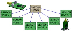
The benefits of vibration sensing for condition monitoring (CM) go beyond taking immediate corrective or preventative actions. The accumulated data can be aggregated and analyzed as “big data,” which is necessary for ongoing machine-monitoring tactics and higher-level decision-making in an IoT world (Fig. 2). For example, the data may show that a specific brand, model, or batch of bearings is showing signs of failing prematurely.
2. Networking of IoT nodes provides a synergistic effect as more accelerometer data or results of analysis are accumulated and correlated.
This may be due to vendor-quality issues, incorrect bearing sizing, installation errors, or inadequate maintenance. By doing the analysis, users can realize many of the possible benefits of Industry 4.0. This new industrial generation promises that factories and production facilities laced with networked sensors for many physical parameters will lead to higher throughout, greater efficiency, reduced downtime, and better insight into operations—all of which can be leveraged to take performance to the next level. Even slight shifts in equipment performance, which are typically difficult to predict in a timely manner, quickly translate into measurable lost productivity.
The Intimate Ties Between Vibration, Acceleration, Velocity, and Noise
Accelerometers measure just that: acceleration. Yet for vibration analysis and CM, it’s often critical to determine velocity, and determine the maximum sensor-noise level that still allows for a meaningful measurement. By basic physics, acceleration is the time derivative of velocity.
Reference 1 briefly explains how to relate the range of vibration magnitude (VMIN and VMAX), frequency (fMIN, FMAX), and acceleration (Apeak, Arms). This analysis is needed when deciding if the range and noise performance of a specific accelerometer is suitable to measure performance with respect to industry standards that assess the severity of vibrations (yes, well-defined standards do exist).
For example, analysis may show that at a minimum vibration frequency of 10 Hz, the noise in the acceleration measurement must be less than 7.18 mg to detect vibration severity in the “good range” for a Class 2 machine, per ISO-10816-1 (VMIN = 1.12 mm/s). Furthermore, multiplying an accelerometer’s noise density by the square root of the noise bandwidth provides a relatively simple method for estimating the total noise in a particular accelerometer and filter configuration.
Traditionally, vibration assessment and monitoring has been accomplished using piezoelectric accelerometers as sensors. These are either mounted to the machinery, or as a part of handheld data-collection tools. While they work in the broad sense, these have several shortcomings:
- Lack of repeatability with handheld measurements, as even slight differences in the sensor probe location or angle will produce inconsistent vibration profiles. Thus, the credibility and consistency of the data, and subsequent analysis, is questionable.
- Lack of real-time reporting: With handheld devices, the data is only available when the technician makes the rounds and downloads the analysis. But even with networked systems, the reporting and analysis may be infrequent, with large time gaps.
- Insufficient analysis: Although the data (even is continuously acquired) is in the time domain, the insight only comes from the frequency-domain analysis; this requires implementation a fast Fourier transform (FFT). Most piezo-based sensor approaches require external computation and analysis of the time-domain data to generate the FFT, thus eliminating the possibility of real-time notification.
- Signal integrity: Even if the sensor is embedded, the piezo-based sensor output is weak and in a noisy environment, so it must be conditioned before further use or interfacing. Alternatively, it must be digitized near the source, thus adding to power needs, complexity, and size—all of which are undesirable in industrial environment. Even the probes of handheld units face the same problem (although on a smaller scale), since the electrical environment is so noisy.
- Single-axis sensing: Many existing piezo-based sensor solutions are single-axis implementations that provide no directionality information, thereby limiting the potential insight into any equipment-vibration profile.
- Sensor calibration and credibility: Even if noise weren’t an issue, how do you assess the performance of the piezo-based sensor itself? There’s no practical self-test that can be invoked on an embedded sensor. For handheld systems, there would need to be a regular calibration and verification cycle using a known stimulus. In either case, the level of confidence and consistency in the data is often not sufficient.
MEMS Accelerometers Redefine the Situation
The limitations of available systems for both embedded and handheld condition monitoring are largely overcome by transitioning from piezo-based sensors to those based on MEMS IC technology. The implications have a system-wide impact that goes beyond the sensors themselves.
The use of MEMS devices for acceleration sensing isn’t new. It was pioneered in the late 1980s and early 1990s, with the development and commercialization at Analog Devices targeting one mass-market application—triggering of automotive airbags on impact. These MEMS devices soon made the spring-loaded, ball-in-tube airbag trigger obsolete. Not only were they smaller, less costly, and more compatible with printed-circuit-board and circuit technology, but it provided the car’s electronic control unit (ECU) much more useful information.
How so? The ball-in-tube was a yes/no impact sensor, while the accelerometer produced a signal proportional to the actual acceleration. Thus, the various acceleration profiles could be assessed, yielding better, more reliable airbag triggering with fewer false or missed positives. Moreover, the MEMS device could be electrically stimulated and implement a comprehensive self-test cycle.
3. MEMS-based accelerometers pack an amazing number of functions and features into tiny IC packages, and with high-end specifications. Accelerometer experts from just a few decades ago would likely be astounded.
This MEMS accelerometer technology was then extended to meet other needs. For example, the single-axis IC was soon enhanced with two- and three-axis versions, which were size- and cost-effective for applications ranging from inertial measurement units (IMUs) to sensing for machine condition (Fig. 3).
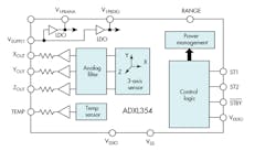
4. The three-axis ADXL354 MEMS analog-output accelerometer from Analog Devices is a highly integrated device, with tight performance specifications, low power, and low size—all virtues for condition monitoring in IoT and Industry 4.0 settings.
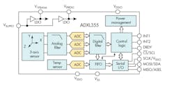
Two examples of the rapid evolution from a basic one-axis, analog-output accelerometer for airbags to a more advanced ICs are Analog Devices’ ADXL354, a low-noise, low-drift, low-power three-axis accelerometer with analog output (Fig. 4), and the similar ADXL355, but with digital output (Fig. 5). Both are housed in packages measuring just 6 × 6 × 2.1 mm. But their performance is impressive despite the diminutive size, with noise density (for all axes) of just 20 µg/√Hz (ADXL354), and 0-g offset vs. temperature (again, all axes) at 0.15 mg/°C (maximum). The digital-output ADXL355 includes 20-bit analog-to-digital conversion, SPI and I2C interfaces, and user-programmable high- and low-pass digital filters.
5. The sensors and front end of Analog Devices’ ADXL355 is almost identical that of the ADXL354, but the IC adds analog-to-digital conversion and serial I/O.
These MEMS ICs also offer a major advantage over piezo-based accelerometers: They include full electromechanical self-test of the sensing element and circuitry. In addition, their low current requirements of 150 µA (ADXL354) and 200 µA (ADXL355) in measurement mode and 21 µA in standby mode make them an excellent fit for wireless IoT installation as well as embedded designs. Both the analog- and digital-output ICs operate from a single 2.25- to 3.6-V supply and are specified over the −40 to 125°C temperature range.
MEMS-based accelerometers offer other benefits in CM applications, in addition to their unique self-test. They can be easily networked for real-time data analysis. Their small size and low power make it very practical to use them paired with a low-power microcontroller for a truly localized vibration sensing and analysis solution, where the FFT and resultant decisions are done at each sensor. This means that the monitoring unit can report deviations, conclusions, alarms, and exception data, but not every reading—and do so in real time.
This is in sharp contrast to periodic “walk-around” data collection with after-the-fact (and perhaps too late) analysis. The real-time aspects of the FFT and associated analysis algorithms means that worrisome trends can be detected earlier, before they become problems.
The small size of the sensors and even a complete sensing subsystem ensures that vibration sensing can be done on multiple machine locations, rather than just one or two that are hopefully, but perhaps not, representative of the entire machine. The data-analysis algorithms can even take into account more sophisticated aspects such as the normal lifecycle shifts in performance that are expected as systems age, bearing raceways and balls wear and accommodate each other, and operating temperature changes. They can also time-correlate data from multiple axes for more sophisticated conclusions.
References
1. Mark Looney, Analog Devices, “MEMS Vibration Sensing: Velocity to Acceleration”
2. Bob Scannell. Analog Devices, Technical Article MS-2507, “Enabling Continuous and Reliable Process Monitoring with Wireless Vibration Sensors”
3. Dr. S. J. Lacey, Maintenance & Asset Management, “An Overview of Bearing Vibration Analysis”
4. H. Saruhan, et al, Journal of Applied Research and Technology, “Vibration Analysis of Rolling Element Bearings Defects”
Related References
- Vibration Rectification in MEMS Accelerometers
- The Five Motion Senses: Using MEMS Inertial Sensing to Transform Applications (PDF)
- Next-Generation Condition-Based Monitoring—Technologies and Solutions for Industry 4.0 (PDF)
Sponsored Resources:
