Improve CAN and CAN-FD Systems with Superior Isolation, Protection
Download this article in PDF format.
The controller area network (CAN) is a very popular serial data bus widely used in automobiles, factory automation, and other industrial applications. A newer enhanced version, designated CAN-FD (flexible data-rate), provides higher speeds and other improvements.
As many designers have discovered, CAN often requires electrical isolation between nodes and protection from high-voltage transients that regularly occur in automotive and industrial environments. Some recently announced CAN transceivers are now available to deliver the latest CAN-FD performance along with the essential isolation. Protection solutions are also available in the form of external discrete components connected to the bus.
Sponsored Resources:
- Isolate your CAN systems without compromising on performance or space
- How to isolate signal and power in isolated CAN systems?
- How to design isolated CAN systems with correct bus protection
CAN Primer
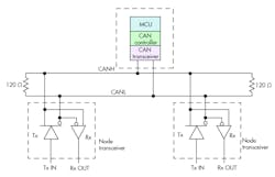
CAN is a serial interface standard developed by Robert Bosch and blessed by the Society of Automotive Engineers (SAE) back in the 1980s. Since then, because of its flexibility and ruggedness, it’s been widely adopted in vehicles and many industrial applications. The topology is a differential bus using shielded or unshielded twisted pair that can accommodate up to 127 nodes. All of the nodes are transceivers that can send and receive. Standard transceiver ICs are available, but many microcontrollers have an integrated CAN interface (Fig. 1).
1. This CAN bus topology shows an MCU with a CAN interface and other transceiver nodes.
Data is transmitted in frames that include up to 8 data bytes along with an address field, CRC error-detection field, and others. Data rate is flexible and can be as low as 5 kb/s or as high as 1 Mb/s. Maximum bus length is 40 meters at 1 Mb/s. The bus access method is carrier-sense multiple-access with collision detection (CSMA/CD). CAN has a number of variations such as CAN-FD, CANopen, and SAE J1939. It’s also designated as ISO-11898 and ISO-11519 by the International Standards Organization.
CAN-FD (ISO-11898-1) is a recent version that bumps the data rate up to 5 Mb/s, making the system more responsive to real time applications that require lower latency and more determinism. A larger frame now carries up to 64 bytes of data.
The Need for Isolation
Besides the widespread automotive applications, CAN systems are deployed in industrial automation, ac and servo motor drives, PLC communications, telecom power supplies, solar inverters, HVAC systems, elevators, and EV charging equipment. Some of these use cases have both high- and low-voltage segments that must be isolated from one another to prevent damage to the lower voltage components.
High-voltage motors, switches, power supplies, and other equipment can generate transients of hundreds or thousands of volts. The MCU controlling the system could potentially be destroyed by some high-voltage signal getting into the low-voltage subsystem. The way to solve this problem in a CAN system is to use isolated transceivers and separate power supplies with their own ground return.
Achieving Isolation
In a modern CAN system, you must isolate both signal and power. Isolation is implemented in the transceiver, but its effects are lost if the power supplies on either side of the isolation barrier are simply connected together.
Many newer CAN transceivers use capacitive isolation between the data inputs and outputs and the bus connect circuits. Two layers of silicon dioxide form two series-connected capacitors over which the data will travel between two separate circuit die—all interconnected within one package.
An example is Texas Instruments’ new isolated CAN transceiver, the ISO1042, which boosts capacitive isolation and protection for virtually any industrial and automotive design. The device, which meets the ISO 11898-2 and ISO 11898-5 physical layer standards, supports standard CAN up to 1 Mb/s and CAN-FD up to 5 Mb/s. Bus fault protection voltage is ±70 V and the common-mode voltage range is ±30 V. The supply voltage range is 1.7 to 5.5 V. Logic levels supported include 1.8, 2.5, 3.3 and 5.0 V. The ISO1042 comes in SOIC (8) or SOIC (16) packages.
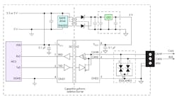
Implementing a separate power supply provides additional isolation. Figure 2 shows one approach using Texas Instruments’ devices. The SN6505 is an oscillator/driver circuit that provides a 100-kHz signal to a transformer that adjusts the voltage to an appropriate level, where it’s rectified and filtered into a dc voltage. The transformer provides the necessary supply isolation. An LDO (such as the TI TPS 76350) provides regulation and power to the CAN transceiver. The node transceivers and the MCU CAN interface connect to the bus via the CANL and CANH differential lines.
2. Here’s what an isolated CAN node looks like with an isolated supply and isolated transceiver.
Various options (both discrete and integrated) are available to simplify the design process of isolated CAN subsystems, and isolate CAN signals and power.
CAN Bus Protection
Isolated systems provide normal protection to the ICs. However, in some environments, electrostatic discharge (ESD) may be a problem—large ESD transients on the bus will typically damage the transceivers. For that reason, some form of bus protection is needed. External ESD protection either isn’t designed in at all, or the protection device is chosen in a way that doesn’t pair well with the transceiver. It’s imperative for the protection device to be chosen to interface in a compatible way with the transceiver.
The best protection solution is to use transient-voltage-suppression (TVS) diodes connected from each bus line to ground (Fig. 2, again). These diodes are effectively two back-to-back Zeners with a high-voltage breakdown voltage level. The maximum voltage rating of the transceivers varies with the device.
The TI ISO105 transceiver can withstand transients in the −27- to +40-V range. The TI ISO1042 can handle spikes up to ±70 V. The TVS maximum breakdown should be less than these values, but higher than the operational voltage of the signals on the bus. The two bus logic levels are usually less than one half the supply voltage (0) and the supply voltage (1).
Note that adding the TVS diodes does provide ESD protection, but these diodes also add capacitance to the bus that will limit the upper data rates. Keep any additional capacitance below 50 pF.
Sponsored Resources:


