Download this article in PDF format.
Conferences and tradeshows are a staple of Silicon Valley, with no shortage of billboards along the Highway 101 corridor between San Francisco and San Jose announcing the next date and location. As waves of cargo pants, suit jackets, and earbuds trudge around the exhibit halls between sessions, it’s becoming increasingly hard to attract their attention.
Designing and implementing demos for these events has always been a large part of my electrical engineering career, and I very much enjoy the challenge. Advances in embedded system technology—and more specifically, new sensor technology—is a fairly mundane subject, and coming up with compelling demos that generate interest isn’t an easy task.
Recently, I set my sights on creating an interactive demo that brought a complete sensor-based system together. The demo needed to use at least two of the three pillars of good demo design: sight, sound, and motion. Previous experience taught me to scale down the remaining pair of pillars, which are explosions and lasers mounted on sharks.
Luckily, we now live in the world of rapid prototyping thanks to companies like Arduino, MikroElektronika, and Adafruit. I use products from these companies all the time to build up the systems that I use for teaching sessions and the evaluation of new products. Fortunately for me, when I started this demo, Microchip had just launched a promotional campaign with MikroElektronika around their click boards, so I had a few of them laying around. I had a 10DOF Click that has two really nice Bosch sensors on it. Specifically, it has the BNO055 9-axis inertial measurement unit (IMU) and BMP180 digital pressure sensor.
We’re close to sea level here in San Jose, and the floor of the convention center is pretty flat, so the pressure-sensor data stream was going to be rather boring. Having a complete 9-axis motion sensor was a whole different story. I also had a few Arduino UNO click shields in my office that I used for this demo. The UNO click shield, as per its name, allows a MikroElektronika Click board to plug into the Arduino shield standard.
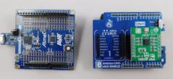
1. The ATmega328P Xplained Mini board (left) is combined with Click Arduino shield (right).
The last piece of the hardware puzzle was an ATmega328P Xplained Mini board (Fig. 1). Turning this board into an Arduino UNO-like platform is just a matter of programming the bootloader, but I had a more elegant solution in mind. This evaluation board also has the footprints to accept Arduino pin socket headers in the standard pattern, and I had those headers available as well. While I wanted to avoid a lot of hardware modification, this was a quick soldering task.
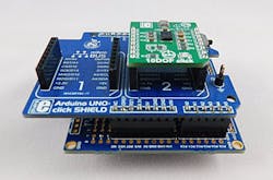
It seemed like everything would just plug together (Fig. 2). I knew that the UNO click shield would route the BNO055 sensors I2C signals to the right place on the Arduino. However, there was another basic problem to overcome. The 10DOF Click is a 3.3-V-only board, and the 328P Xplained Mini default configuration is 5-V operation from a USB connection. However, the Microchip tools team had already taken care of the 3.3-V issue by providing a LDO on the 328P Xplained Mini that can be called into service using a few jumper pads.
2. This is what full stack looks like with the MikroElektronika 10DOF Click, Arduino Uno click shield, and ATmega328P Xplained Mini board plugged together.
All three boards were plugged together and after a quick power-up sanity check, I now had a viable sensor/microcontroller stack powered at my desk with none of the magic smoke from the ICs escaping anywhere.
Demo Application
After the setup, now it’s on to the hard part—the demo application.
I was already familiar with the Bosch BNO055 9-axis IMU from previous projects, so I already had some test code from Adafruit to validate the basic data stream from all three motion sensors. Adafruit also supplies a comprehensive library for the BNO055, which contains the test code I was using.
The BNO055 is a fairly powerful IMU that’s able to provide not only basic raw data from the accelerometer, gyroscope, and the magnetometer, but complete sensor solutions in Euler angle and quaternion formats. The Adafruit test code was already in sketch form and was written against the exact same BNO055 device. Adafruit is one of my go-to places when I’m pulling together systems for demo or teachings. Not only are the hardware designs solid, but the documentation is top level. Every product is released with an excellent amount of collateral including app notes and hookup guides.
Since I was using the Arduino sketch import function in Atmel Studio 7, programming the Arduino bootloader into the mega328P Xplained Mini board wasn’t needed. As expected, the test code from Adafruit imported without issue into Atmel Studio 7. Working with Studio 7 gave two real advantages in bringing this demo to life, in addition to being able to leverage the large amount of codebase already out in the open domain.
The first and most important value-add is the ability to perform source-level debug on an Arduino sketch, including being able to use breakpoints and inspect/modify data in memory without needing to use the Serial.print() function at all. This amount of visibility and control, which is a normal part of professional embedded development systems, allows me to create root cause and squash all of those tiny annoying bugs that creep up when one starts throwing demo code together quickly.
Secondly, because the primary data stream out of the Xplained Mini board was the CDC USB port, I didn’t need to contaminate the IMU data stream in any way with debug information. The only real issue I saw at the time was a mismatch I2C address, but the BNO055 board from Adafruit and the 10DOF click schematics indicated that this wouldn’t be an issue.
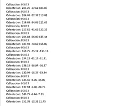
I downloaded the code, started up my terminal console application on the laptop, and was pleasantly greeted by the following ACSII data stream.
Perfect.
Apart from some calibration issues on the sensors themselves, the data made sense in both magnitude and response to waving the boards around on its USB leash. I’m now about halfway there in that I have a working 9-axis IMU sending me a reasonable telemetry data stream. It’s an ASCII character-based stream, so a little less efficient in payload, but perfect for a demo environment because I can split the system in half to show what basic IMU data looks like.
I did, however, want to implement something a lot more interesting on the PC screen than a wall of numbers scrolling by. The tradeshow I was attending didn’t have a large number of tax accountants there, so something a little more elegant than columns of numbers seemed necessary. A typical demo application for motion sensors is to plot the gravity vector or three separate axis graphs representing the gravity vector. It gets the point across but doesn’t really demonstrate the full power of the BNO055. There’s a better way to show off the sensor fusion going on inside that device.
Again, Adafruit to the rescue. When one visits the BNO055 breakout board webpage, there’s a short video showing a 3D Bunny following the motion of a wireless connected breadboard. This “bunny” code (Fig. 3) is also the first example sketch that appears under the Adafruit BNO055 Library Example list. The bunny sketch example is paired with another application (also called a sketch) that runs in Processing.
3. “Bunny” code is the first example sketch that appears under the Adafruit BNO055 Library Example list.
I was already familiar with Processing. It’s a great language for embedded designers like me to get data on a PC screen, beyond just ASCII text in a console program. Processing also was the base for Wiring, and Wiring is the base language for Arduino. Everything is flowing together nicely. The import of the Arduino bunny example sketch into Atmel Studio 7 went flawlessly, as expected, and after installing a few more support packages for Processing on my main development system, I decided to verify the data stream with a terminal console before starting the bunny sketch:
The data-stream format confirmed I was working with Euler angles and not quaternions. That was important because I was also pretty sure that the gimbal lock issue would show up unless the developers of the rotation library took care of that problem.
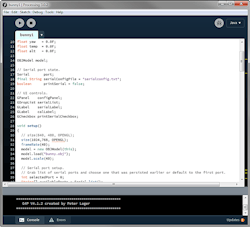
A quick look at the 3D bunny code in Processing (Fig. 4) told me that the size of the object window was 640 × 480 pixels. I don’t see a lot of 20-in. CRT VGA monitors at tradeshows anymore, and even the pile of vintage electronics in my garage is CRT-free, so I bumped up the resolution to a modest 1024 × 768 and tweaked the offsets and scaling accordingly.
4. The 3D bunny code in Processing.
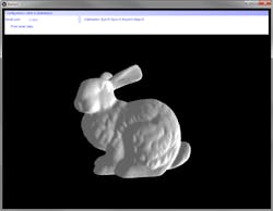
The bunny rotated as expected as I rotated the board stack in space (Fig. 5).
5. I clicked the play button, and the bunny rotated the board stack in space.
I now had an interactive demo that met all of my base requirements for a quick tradeshow demo:
- It was easily reproducible, quick to set up, and inexpensive
- It can be deconstructed into its system components
- Apart from the power-supply mod on the Mega328P Xplained Mini, there weren’t any blue wires or hardware hacks involved.
The demo did indeed demonstrate the gimbal lock effect—the rotation of the bunny made a step jump whenever the orientation of the board neared the 90° or 180° limits on one axis. It’s much better to show that concept directly than to explain the math behind the problem.
The demo itself is pretty straightforward. What really caught me by surprise was the low effort and short period of time that it took to go from a stack of boards to a full 3D rotation demo on my laptop. Ultimately, it took me around an hour to get all of this going. The hardware aspect of the demo uses two different hardware prototyping standards: Arduino Shield and mikroBUS. The software part employs three development platforms: Arduino IDE, Atmel Studio 7, and Processing.
System-wise, everything plugged together in a sequence that made sense and just worked. I was a system apps engineer for a MEMS gyroscope company for a few years in the past, and a demo like this usually took the better part of a week.
It was also clear that the next step was to add some wireless connection to the demo since I had a spare mikroBUS socket waiting for some type of RF-based click board from MikroElektronika. The gimbal lock issue also needed to be looked at but, at the end of the day, I had a demo ready that I could carry in my laptop backpack.
It’s clear that the age of rapid prototyping is upon us. Companies like MikroElektronika, Adafruit, and of course Microchip, are putting a large amount of effort into allowing designers to bring concepts together in an impressively short period of time. The cross-compatibility of the hardware prototyping standards mean less time at the soldering station and more time refining design. Example solutions are being handed out on plates these days—don’t be afraid to reach out and take one.
Bob Martin is Senior Staff Engineer at Microchip Technology.
References:
Hardware
- 10DOF click board: https://shop.mikroe.com/10dof-click
- Arduino UNO Click Shield: https://shop.mikroe.com/arduino-uno-click-shield
- ATMEGA328P Xplained Mini: http://www.microchipdirect.com/ProductSearch.aspx?Keywords=ATMEGA328P-XMINI
- Adafruit 9-DOF Absolute Orientation Sensor IMU Fusion Breakout – BNO055: https://www.adafruit.com/product/2472
Software
- BNO055 Arduino Library, Test code and 3D Bunny code: https://github.com/adafruit/Adafruit_BNO055
- Processing: processing.org

