Microelectromechanical-systems (MEMS) technology such as bulk acoustic wave (BAW) adds benefits to factory-automation systems because of its ability to synchronize the clock and time between fast-moving components. BAW is a microresonator technology that enables the integration of high-precision and ultra-low-jitter clocks. The technology is less bulky than external quartz crystals and delivers a cleaner and more accurate clock source. Fast-moving robotic arms in collaborative robots (cobots) benefit from BAW technology because motion synchronization over multi-axis motors and sensors is essential for high-speed motion control, while also being suitable in pick-and-place and injection molding machines.
Collaborative robots (cobots) are becoming more popular in today’s factory automation and production assembly lines because of their ability to work simultaneously with humans. This new capability is in part enabled by a wide range of accurate sensors with integrated safety functionality that have increasingly good perception and awareness of the factory area around them.
Cobots need to move slowly and gracefully to keep human colleagues safe, but also need to operate as fast as possible to effectively perform tasks. If a cobot detects a malfunction in its system or if the safety of the human is jeopardized, the robot needs to act fast and enter a “safe state” to protect the human and prevent damage to the surrounding tools and work space.
Leveraging BAW
This article looks at how a microelectromechanical-systems (MEMS) technology called BAW benefits factory-automation systems due to its ability to synchronize clock and time between fast-moving components. The microresonator technology makes it possible to integrate high-precision and ultra-low-jitter clocks into phase-locked loops (PLLs) with jitter cleaner, which are used in synchronous Ethernet systems.
The moving arms in cobots benefit from BAW technology because motion synchronization over multiaxis motors and sensors using Ethernet is essential for high-speed motion control. Not only do cobots benefit from this technology, so does other fast-moving machinery like newspaper printing machines, injection molding, computer-numeric-control (CNC) machines, 3D printers, and pick-and-place machines.
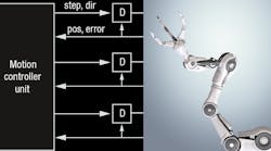
Figure 1 shows the system architecture of cobots with multiaxis motors, sensors, and actuators. The system comprises the cobot’s motion controller connected to drive stages (D) with connected motors (M) to position the arms, and sensors to detect the arm position and the pressure of tool handling. Sensors (like safety curtains) and actuators can handle the tools that perform workpiece assembly and modification.
1. A motion-controller unit can use star topology (left) or the newer industrial Ethernet line topology (right).
Previous generations have used a star topology of step and direction (dir) signals to control the motors, sensors, and actuators from the motion controller unit. In parallel, a serial fieldbus interface for feedback signals (FB) such as encoder data, current measurement of the motor stages, temperature, errors and faults, as well as other data like emergency stop button and safety fence conditions, also reads back position (pos) and errors.
The motion-controller unit runs a closed-loop motor-control algorithm. It updates the motor driver with new data every 62.5 µs (16 kHz). The updates are based on the measured current of the motor shunts, the position of the motor shaft read by the encoder, and other data. The closed-loop motion control typically requires a fast exchange of process data.
New cobot systems are replacing the old star and serial fieldbus interfaces (Figure 1, left) and moving to an industrial Ethernet line topology (Figure 1, right). With industrial Ethernet protocols reaching gigabit speeds and enabling updates of the motor-controller unit below 62.5 µs, the motion control and feedback data are now sent over the same Ethernet wire, reducing cabling and fieldbus complexity.
Clock and Time Synchronization Challenges
Synchronous Ethernet (SyncE) International Telecommunication Union Telecommunication Standardization Sector G.8262 technology plays an essential role when it comes to simplifying time and clock synchronization in order to enable fast and accurate motor control. SyncE provides a mechanism to distribute the master clock frequency (such as 25 MHz) over an Ethernet cable. The IEEE 1588 Precision Time Protocol or another time-synchronization standard built into one of the industrial Ethernet protocols—examples include EtherCAT distributed clocks or PROFINET Precision Transparent Clock Protocol—can handle the required time synchronization.
Let’s come back to SyncE, where BAW technology provides a significant advantage when many Ethernet devices are connected in a line topology. Figure 2 shows a SyncE line topology with the distribution of the reference clock signal over multiple Ethernet nodes.
2.Shown is the SyncE line topology over multiple Ethernet nodes with a distribution of the reference clock signal.
SyncE technology works like this: Each Ethernet physical-layer (PHY) transceiver requires a clock source of typically 25 MHz. This clock is used by the first Ethernet PHY (transmitter) to transmit Ethernet frames between the two Ethernet nodes. The receiving Ethernet PHY (receiver) will lock onto the transmit clock and recover the transmitter’s 25-MHz clock.
Some industrial Ethernet PHYs, like the Texas Instruments (TI) DP83869, can output the recovered 25-MHz clock on an external pin. The 25-MHz clock is fed into a PLL with an integrated jitter cleaner, which generates a jitter-cleaned version of the 25-MHz recovered clock. This recovered and jitter-cleaned 25-MHz clock is provided to the second Ethernet PHY (transmitter) in the second Ethernet node. When using the SyncE line topology, the reference clock signal is distributed to each SyncE node.
The PLL with Jitter Cleaner
The PLL with jitter cleaner plays an essential role in the SyncE architecture. It must clean out frequency and phase jitter introduced by Ethernet PHY transmitter and receiver devices. BAW technology integrated into the PLL with jitter cleaner minimizes propagated jitter over Ethernet nodes.
BAW Technology
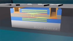
A BAW resonator is a thin-film resonator similar to a traditional quartz crystal. As shown in Figure 3, a piezoelectric film is sandwiched between two metal films and several other layers to confine mechanical energy. This structure traps the acoustic energy while creating a resonator element with very low loss and a high quality factor. Historically, BAW resonators have been used for radio-frequency filters on the front end of wireless transceivers in mobile devices.
3. A bulk acoustic wave (BAW) resonator is a thin-film resonator that’s similar to a traditional quartz crystal.
BAW technology is now integrated into products using the BAW resonator as a low-noise voltage-controlled BAW oscillator to generate ultra-low-noise clocks.
Using a BAW resonator as described above provides the following advantages for SyncE systems:
- The high quality factor (approximately 1,000 at 2.5 GHz) supports ultra-low jitter.
- A high resonant frequency (2 to 3 GHz) supports divide down to achieve multiple clock frequencies (for example, a 2.5-GHz BAW can be divided down to generate 156.25-MHz, 125-MHz, and 100-MHz clocks).
- Superior root-mean-square jitter has no impact from external sources and is easy to design with: <60-fs RMS (12 kHz-20 MHz) at 156.25 MHz and <30-fs RMS (12 kHz-20 MHz) at 1.25 GHz.
- Hitless switching between the local 25-MHz clock and the Ethernet PHY’s recovered clock.
- Immunity to mechanical shock introduced by the movement in cobot arms.
The jitter-cleaned 25-MHz clock generated by the LMK05318 is also used by the Ethernet media access control (MAC) and microprocessor unit (MPU) to minimize synchronization jitter between the Ethernet PHY and MAC. Furthermore, the MPU uses the recovered clock to generate pulse-width modulation (PWM) for the motor driver, start current measurement sampling, and read out encoder data of the motor position. When all of the clocks are synchronized across the Ethernet nodes, the motion controller in a cobot system synchronizes the generation of the PWM signals for motors.
Summary
SyncE simplifies clock and time synchronization challenges in a cobot over multiple Ethernet nodes. The PLL with jitter cleaner plays a significant role in a SyncE node for distributing accumulated jitter over multiple Ethernet nodes. BAW technology integrated into the PLL with jitter cleaner minimizes distributed jitter when passing the recovered clock from Ethernet node to Ethernet node.
The jitter-cleaned recovered clock used by the MAC and MPU helps synchronize clock and time over a time-synchronization protocol like IEEE 1588 PTP, enabling cobots operating in a fast and precise manner to effectively perform tasks and work on production goods.
TI’s LMK05318 is a PLL with jitter cleaner that uses BAW technology to remove distributed jitter. An Ethernet PHY device such as the DP83869 outputs the recovered clock signal. SyncE systems using those components enable the distribution of a low-jitter master reference clock source.
Thomas Mauer is System Engineer (MGTS), Factory Automation and Control & Robotics at Texas Instruments.


