10BASE-T1L Single-Pair Ethernet Cable Reach and Link Performance
What you’ll learn:
- The ins and outs of 10BASE-T1L Ethernet.
- How cable length and link technology affect performance.
- Insight into how diagnostic and other tools can help maintain efficiency and peak performance.
As 10BASE-T1L Ethernet emerges across various industries, more applications come to light, each bringing new challenges to be addressed to successfully deploy the technology. A common requirement is support for a wide range of cable types. In some cases, these cables have been used in legacy communication systems and are often found in existing installations. The flexibility of the cable definition in the 10BASE-T1L standard creates an advantage over other technologies by allowing for the reutilization of such cables.
This flexibility raises common questions, such as whether 1 km can be achieved with any cable or whether performance is the same independent of the type of cable. Link performance and reach depend on the cable’s characteristics, which, in turn, depend on the construction of the cable. This article summarizes the cable characteristics relevant to this technology, describes the dependency of cable reach as a function of these characteristics, and provides a list of cables that have been tested.
Advanced Physical Layer and 10BASE-T1L
The advanced physical layer (APL) specification and IEEE 802.3cg 10BASE-T1L specification (Fig. 1) are two different standards that are related, but they should not be used interchangeably. The IEEE 802.3cg standard defines the 10BASE-T1L physical layer for long-reach Ethernet communication over a single twisted pair independent of the application.
The APL standard adds extra specifications and definitions on top of the IEEE 802.3cg so that the same physical layer can be used in process-control applications in intrinsically safe environments. This means that any APL device is compliant with the 10BASE-T1L standard (the data layer, but not the power delivery over the data line), although not every 10BASE-T1L device is APL compliant.
The APL document comprises specifications for the data layer and system definitions, covering aspects such as electromagnetic compatibility (EMC) performance, cable shield connection, and network topology.
For example, as shown in Figure 1, the APL specification defines two types of data links within the same network: the spur and the trunk. The spur links directly connect to the field devices and can’t exceed 200 m in length, operating at 1.0 V p-p transmission levels due to the intrinsically safe environments of the field devices. The trunk, which links field switches or connects upstream to the nearest power switch, can extend up to 1,000 m and operates at 2.4-V p-p transmission levels.
>>Download the PDF of this article, and check out the TechXchange for similar articles and videos
In other 10BASE-T1L applications, such as those in building automation technologies, APL compliance isn’t required. Thus, the concepts of spur and trunk aren’t relevant. In fact, network topologies in this technology can vary from star to line to ring or a combination of these.
The transmission level may be chosen based on power limitations or noise immunity, independent of where the sensor or network switch is placed. This allows for more flexibility in the use of cables, as the 2.4-V p-p transmission level can be used independent of where the link is located, enabling higher tolerance for signal losses in the cable and a less strict nominal cable impedance. This is explored in more detail in the following sections.
Cable Characteristics Specified in the Standards
The link segment characteristics that a cable must meet to be IEEE 802.3cg compliant are specified in subclause 146.7 of the same document. This subclause defines the limits of the insertion loss, return loss, maximum link delay, differential to common-mode conversion (for unshielded cables), and coupling attenuation (for shielded cables).
In addition, for applications involving intrinsic safety, such as installations in explosive zones (Zone 0, highly explosive; Zone 1, likely to produce a fire or explosion; Zone 2, possible for an explosion or a fire to occur though not as likely), the APL specification document adds extra rules and definitions for the operation of the 10BASE-T1L physical layer. It includes definitions for cabling: cable classification, maximum cable length for spurs and trunk links, shielding, etc.
Insertion Loss
The insertion loss in cables, measured in decibels (dB), reflects the signal reduction along the transmission line (cable). It’s calculated as the ratio of the transmitted signal’s power to the received signal’s power at the cable’s end. This loss, or attenuation, increases with the cable’s length and the signal’s frequency.
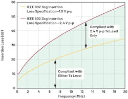
According to the IEEE 802.3cg standard, the maximum permissible insertion loss varies with the transmission levels: It’s higher for 2.4 V p-p than for 1.0 V p-p, accommodating the different signal strengths and their respective requirements.
IEEE 802.3cg Specification
Both limit curves are specified in the IEEE 802.3cg subclause 146.7.1.1 as follows: For the 1.0-V p-p transmission level:
For the 2.4-V p-p transmission level:
In both equations, f is the frequency given in MHz and 0.1 MHz ≤ f ≤ 20 MHz. Figure 2 shows both insertion loss limits corresponding to the 1.0-V p-p and 2.4-V p-p transmission levels.
APL Classification
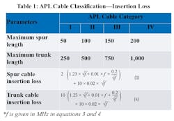
The APL cable specification classifies cables into four categories based on their insertion loss, which dictates the maximum allowable link length for either spur or trunk data links. These categories also comply with the IEEE 802.3cg 10BASE-T1L cable specification.
The insertion loss limits for 1.0 V p-p and 2.4 V p-p are aligned with the operational requirements for spurs and trunks, respectively. Spurs must operate at 1.0 V p-p, adhering to the corresponding insertion loss limit, while trunks operate at 2.4 V p-p, following the higher insertion loss limit. Table 1 shows all APL cable categories and their definitions around cable length and insertion loss curves.
Notice that Equation 4 is identical to Equation 2 from the IEEE 802.3cg 10BASE-T1L specification, while Equation 3 is less than half of Equation 1, thus specifying a more conservative limit for cables connecting to spurs.
The correct understanding of Table 1 is that for a given type of cable to be APL Category IV, the insertion loss of a 1,000-m sample of that cable must be below the threshold set by Equation 4. If this isn’t the case, the cable doesn’t meet Category IV standards.
For a cable to be classified as APL Category III, its 750-m sample must have an insertion loss below Equation 4. If it fails to meet this criterion, but a 500-m sample of the cable does meet the requirement, then the cable qualifies as APL Category II. Should the 500-m sample fail, but a 250-m sample succeeds in meeting the Equation 4 threshold, the cable is classified as APL Category I. If a cable doesn’t meet any of these criteria, then it’s not APL compliant.
Return Loss
In an ideal scenario, when a signal is transmitted through one end of a cable, it should be completely absorbed by the load at the other end. However, as previously discussed, the signal is diminished due to the cable’s insertion loss, and some energy is also reflected back toward the source. These reflections, caused by impedance mismatches between the transmitter and the cable or along the cable itself, can occur at any point.
The return loss of a given cable quantifies the amount of signal reflected back to the source and is commonly measured in decibels. Return loss is calculated as the ratio of the transmitted signal to the reflected signal and, like insertion loss, varies with frequency.
Assuming a cable is high quality, its impedance would be consistent throughout, minimizing impedance mismatches except at the connection points with transceivers. This isn’t true in the cases where a given cable link has faults along its length due to damage or poor construction. However, for the objective of this article, this scenario will be neglected.
Unlike the IEEE 802.3cg 10BASE-T1L insertion loss specification, the return loss specification is independent of the transmission level. This is a direct result of the fact that the return loss of a properly terminated cable doesn’t depend on its length. Therefore, regardless of whether a cable is 200 or 500 m long, return loss should remain consistent, barring variations due to manufacturing processes or environmental conditions like humidity and temperature.
The IEEE 802.3cg standard specifies the minimum return loss curve (vs. frequency) that a cable must comply with as follows:
where f is the frequency in MHz.
APL Specification
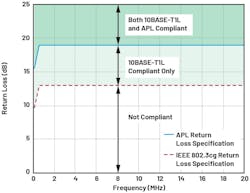
The APL specification also defines the minimum return loss for a cable to be APL compliant. This specification is much simpler than for insertion loss, as it doesn’t make any differentiation between the two transmission levels of the transceiver:
where f is the frequency in MHz.
Notice that the APL cable return loss specification is stricter than the IEEE 802.3cg specification, as it adds 6 dB of extra margin. Figure 3 shows that any cables with return loss are compliant with the APL specification and comply with the 10BASE-T1L return loss specification. However, not every cable compliant with the 10BASE-T1L return loss specification is compliant with the APL specification.
Maximum Link Delay
Link delay refers to the time that a signal takes to travel from one end of the cable to the other end of the same cable. This is a result of the construction of the cable and can show variations in temperature. Link delay may also be expressed as a function of the nominal velocity of propagation (NVP) of the cable, which is defined as the ratio between the speed of the signal through the cable and the speed of light.
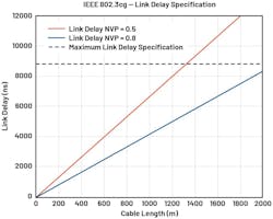
Cable NVPs are always below 1.0 and, for most cables, between 0.6 and 0.8. In some cases, cables may have NVP values closer to 0.5, which means that the cable’s link delay is longer for a given cable length.
The maximum link delay specified in the IEEE 802.3cg for 10BASE-T1L is a fixed number that corresponds to a 1,589-m cable with an NVP of 0.6. This leads to a maximum link delay of 8834 ns:
Mode Conversion and Coupling Attenuation
The insertion loss and return loss of the cable are the main parameters that determine the cable performance under normal conditions. However, industrial applications require systems to withstand environments with high electromagnetic interference (EMI). These can range from constant frequency tones coupling to the cable to high-frequency, high-energy pulses that only occur sporadically.
Regardless of the interference, a 10BASE-T1L or APL communication link must survive and avoid data losses. Since most of this EMI comes from external sources, one of the main coupling mechanisms is the long single-pair cable. Thus, the cable characteristics play an important role in the overall electromagnetic immunity.
Coupling Attenuation—Shielded Cables
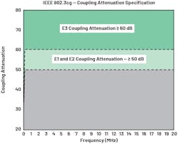
For shielded cables, the IEEE 802.3cg standard defines a minimum coupling attenuation. This relates to the maximum amount of signal that couples to the data pair differentially. In a shielded cable, this is a result of the quality and coverage of the shield and the symmetry of the wires within the same pair. Different shields will, hence, have different responses. For instance, a cable with a foil shield and drain wire will likely exhibit a different performance compared to a cable with a braid shield that has 90% coverage.
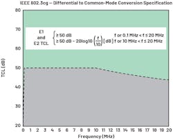
Figure 4 shows the IEEE 802.3cg specification for systems installed in electromagnetic environments E1, E2, and E3. E1 corresponds to devices deployed in electromagnetic environments such as those found in residential, commercial, and light industrial buildings. E2 corresponds to devices deployed in electromagnetic environments in other industrial buildings. E3 corresponds to devices powered from the battery of a vehicle.
Differential- to Common-Mode Conversion—Unshielded Cables
Assuming that both wires in the same pair are ideal and symmetric, signals should couple equally, resulting in a common-mode signal that the MDI circuitry in the 10BASE-T1L signal path can more effectively filter. However, asymmetries between the wires may cause some of the common-mode signal to manifest as a differential signal across the transmission line.
If this signal falls within the 10BASE-T1L bandwidth of interest (100 kHz to 20 MHz) and is sufficiently large, it could disrupt the auto-negotiation process or data transmission. Moreover, this asymmetry might convert part of the differential signal of 10BASE-T1L into a common-mode signal, increasing cable losses and potentially degrading performance.
To mitigate these issues, the IEEE 802.3cg standard specifies a minimum differential- to common-mode conversion (TCL) based on the electromagnetic environment in which the cable operates. Figure 5 shows the specification for electromagnetic environments E1 and E2.
Characteristics Dependency over Length
In the IEEE802.3cg 10BASE-T1L standard, cable characteristics aren’t defined for a specific length, leading to frequent inquiries about maximum reach and compliance. For instance, a 1,000-m length Cat5/Cat6 is typically not compliant with the 10BASE-T1L standard because its insertion loss exceeds the limits set by Equations 1 and 2, whereas approximately 700 m of the same cable may be compliant.
Insertion Loss Dependency on Cable Length
As suggested earlier, insertion loss represents signal attenuation and is usually expressed relative to frequency. It follows that insertion loss in decibels is directly proportional to the cable length.
This means that a link segment of length k times the length of another cable of the same type has a total insertion loss of k times the insertion loss of the shorter cable. As an example, a 1,000-m sample of cable has an approximate insertion loss curve equivalent to 10X the insertion loss curve of a 100-m sample of the same type of cable.
Return Loss Dependency on Cable Length
Assuming uniform construction throughout its full length (consistent wire diameter, constant spacing between wires, uniform twists per meter, etc.), the return loss of the cable doesn’t vary with length.
This assumption holds reasonably well for the frequency range of 10BASE-T1L communications. However, a cable composed of interconnected segments of the same type might exhibit worse return loss than a single continuous segment due to possible reflections at each connection. For simplicity, this section assumes that the return loss of a given cable type remains constant regardless of length.
Link Delay vs. Cable Length
For a given cable, the signal delay is directly proportional to the cable length. The signal delay through a cable varies across different cable types and is a function of its construction. Typically, cable manufacturers provide this information as a function of the NVP. Equation 8 shows how to calculate the link delay based on the NVP value of a cable.
where L is the length of the cable in question, NVP is the nominal velocity of propagation of the cable, and c is the speed of light.
Figure 6 shows the link delay vs. cable length for two cables, one with an NVP = 0.5 and a second cable with an NVP = 0.8. Notice that even for the low value of NVP, the standard could accommodate a link delay corresponding to over 1,300 m. There’s enough headroom built into the standard to provide robustness and variations over temperature.
Maximum Cable Reach
The primary constraint on cable reach is typically the insertion loss, which is why the APL categories are based on this factor. Insertion loss is directly proportional to cable length, thus setting the cable length limits within the APL categories.
For non-APL applications, the 10BASE-T1L technology allows for more flexibility, supporting both shielded and unshielded cables, cables with more impedance mismatches, reutilization of cabling, etc. In addition, some applications might work with cables that exceed the IEEE 802.3cg standard specifications. To accommodate these applications, Analog Devices’s 10BASE-T1L portfolio includes a significant built-in margin, enabling communication over distances of up to 1,700 m and ensuring robust performance across various cable types.
However, the maximum reach varies from cable to cable, and 1,700 m isn’t achievable for every type of cable in the market. Some cables may exhibit higher signal losses, which leads to a shorter reach.
Maximum Reach and Cable Compliance with the IEEE 802.3cg
If an installation is aimed to be compliant with IEEE 802.3cg, both cabling and PHY devices must meet the standard. This section delves into the specifications for insertion and return loss, as well as the compliance verification process. In addition, it outlines a method to estimate and test the maximum reach of a given type of cable.
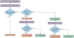
Figure 7 shows how to calculate the maximum reach of a cable. The flow diagram relies on the measurement of the insertion loss and return loss of a sample of the given cable.
Theoretically, the length of the cable should not affect these results; however, in practice, the measurement error increases as the cable’s length decreases. Due to this, the APL specification recommends measuring cables using a 500-m sample. For non-APL applications, the document recommends using at least 100 m of cable to obtain acceptable results.
To ensure compliance, the initial step involves assessing the cable’s return loss across various frequencies. If the return loss falls below the threshold outlined in Equation 5, the cable fails to meet the standards, eliminating the need for further testing.
However, if the cable’s return loss is above the specified curve, the next step is to evaluate the cable’s insertion loss against the benchmarks set in Equations 1 or 2. If the insertion loss exceeds these curves, then the cable is deemed non-compliant.
After the insertion and return losses are verified, the diagram suggests a method to estimate the maximum permissible length that meets the specifications. This is achieved by multiplying the measured insertion loss by a factor k to obtain a curve as close as possible to the one described in Equation 1 for the 1.0-V p-p or Equation 2 for the 2.4-V p-p transmission levels.
By multiplying by factor k, the extrapolation estimates the insertion loss for a cable of the same type but extended to k times the length of the tested sample. The goal is to determine the maximum k where the extrapolated insertion loss curve remains below the required specification curve, adjusting k iteratively during the extrapolation process.
The following example can be used to illustrate this method and assumes the insertion loss and return loss have been measured.
Step 1: Return loss verification
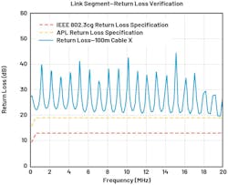
Figure 8 shows the return loss verification of Cable X of a given type and a length of 100 m, as well as the return loss specifications for both IEEE 802.3cg and APL. Note that every point in the measured return loss of the cable is greater than both APL and IEEE 802.3cg return loss specifications. This means that the measured cable complies with both return loss standards.
Step 2: Insertion loss verification
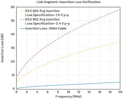
The insertion loss can be verified by plotting the cable’s insertion loss against the specifications (Fig. 9). The insertion loss of Cable X was measured and is shown in solid blue. Notice that this curve is well below both the 1.0-V p-p and 2.4-V p-p 10BASE-T1L specifications plotted in the dotted and dashed red lines.
This means that any 100-m link of this same type of Cable X can be used in 10BASE-T1L links for either 1.0 V p-p or 2.4 V p-p.
Step 3: Calculation of maximum length compliant with the IEEE 802.3cg standard
This section focuses on the IEEE 802.3cg standard and not on the APL classification. However, a similar analysis can be made in accordance with Table 1.
The measured insertion loss can be extrapolated by multiplying each data point by a factor k whereby the resulting curve, when plotted against either the 1.0-V p-p or 2.4-V p-p standard, falls below either of the two curves, depending on the transmission amplitude to be utilized.
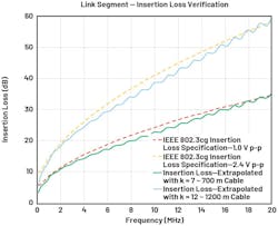
Figure 10 shows the IEEE 802.3cg insertion loss specifications for 1.0 V p-p and the extrapolated curve obtained by choosing k = 7 (green line). The curve in green was obtained by multiplying each data point of the insertion loss of the 100-m cable sample by k = 7. Notice that the extrapolation obtained is just below the 1.0 V p-p specification, meaning that 700 m (resulting from multiplying k = 7 times the cable’s length) is the approximate maximum length compliant with the 1.0-V p-p transmission level in non-APL applications. Any length below 700 m is also compliant with the 1.0-V p-p transmission level specification.
Similarly, Figure 10 shows the IEEE 802.3cg insertion loss specifications for 2.4 V p-p and the extrapolated curve obtained by choosing k = 12 (blue line). This curve was obtained in a similar way as explained above, by multiplying each data point of the insertion loss of the 100-m cable sample by k = 12.
Notice that the extrapolated curve is also just below the 2.4-V p-p specification, meaning that 1,200 m is the approximate maximum length compliant with the 2.4-V p-p transmission level (based on its insertion loss). Any length below 1,200 m will also be compliant with the 2.4-V p-p specification.
The analysis concludes that, based on the insertion loss and return loss criteria, the maximum permissible link segment for this specific cable type in non-APL applications is approximately 700 m for the 1.0-V p-p and 1,200 m for the 2.4-V p-p transmission levels. However, for applications requiring full compliance with the standard, the maximum link segment must not exceed 1,000 m.
This methodology can be applied to other cable types, potentially resulting in maximum compliant link segments of less than 1,000 m. For instance, when similar assessments are conducted on Cat5/Cat6 cables, the typical maximum length compliant with the 10BASE-T1L standard is generally no more than 700 m, although this can vary depending on the specific cable brand and model, as some may offer additional margin.
Cable Testing to Estimate Maximum Reach
Cable testing procedures involve using a vector network analyzer (VNA) to estimate the cable’s parameters and ADI’s EVAL-ADIN1100EBZ evaluation kit to perform Ethernet traffic tests. The evaluation kit features a media converter functionality and provides access to diagnostics features (such as frame generator, frame checker, mean square error, and loopback modes) through its evaluation software.
Testing Procedure
Cable testing includes measuring the insertion and return loss of the cable under test using a VNA. These parameters are then applied to evaluate cable compliance and estimate the maximum cable length that’s compliant with the IEEE802.3cg 10BASE-T1L standard. The maximum compliant lengths correspond to the maximum lengths of the specific type of cable still compliant with the 2.4-V p-p or the 1.0-V p-p insertion loss curves as defined in the IEEE 802.3cg (Fig. 2, again).
Further testing includes connecting two EVAL-ADIN1100EBZ evaluation boards through the cable under test to establish a 10BASE-T1L link. Subsequent link performance tests involve transmitting Ethernet traffic at full bandwidth using the on-chip frame generator. The mean squared error (MSE) of the 10BASE-T1L link is monitored on each EVAL-ADIN1100EBZ board, along with the error count and the number of received Ethernet frames. Tests are marked as passing only if:
- 10BASE-T1L is established successfully.
- The MSE is better than –20.5 dB.
- There are no errors in the received frames during the execution of the test.
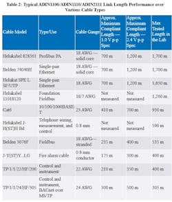
This test is conducted repeatedly for various lengths of the same cable type to determine the point of failure. However, in some cases, the maximum tested length corresponds to the maximum length available in the lab and not necessarily to the maximum reach of the cable.
Similarly, in situations where the increments of cable length exceed 100 m, the identified failure point may not accurately represent the absolute maximum cable length. For instance, if only 500-m segments are available, a successful link might be established using 1,000 m (two 500-m segments connected), but it fails at 1,500 m. Though the true maximum length may be 1,200 m, this specific length isn’t available for testing, so the last recorded data point remains at 1,000 m.
Table 2 shows a variety of cables tested in the lab, the estimated maximum length compliant with the 10BASE-T1L standard for both transmission levels, and the tested lengths at both 2.4 V p-p and 1.0 V p-p using the EVAL-ADIN1100EBZ evaluation board.
Conclusion
The IEEE 802.3cg-2019 standard’s flexible cable definition supports a broad range of cable types previously used in older communication protocols, maintaining extensive reach to connect edge devices seamlessly through Ethernet connectivity without requiring gateways.
Analog Devices’s ADIN1100, ADIN1110, and ADIN2111 include built-in margins to support both standard-compliant and non-compliant cables. While it’s ideal for applications to adhere to IEEE 802.3cg or APL specifications, particularly in process control, the reality is that many systems need to reuse existing wiring to reduce deployment costs.
This built-in headroom enhances data link robustness and facilitates the adoption of 10BASE-T1L technology with various cable types, including those already installed for other communication protocols. Such flexibility helps ensure that ADI’s 10BASE-T1L devices can maintain consistent cable reach for both 1.0-V p-p and 2.4-V p-p transmission levels.
Furthermore, Analog Devices’s 10BASE-T1L diagnostics tools, such as the frame generator, frame checker, link quality indicator through the mean square error, and the cable fault detector with TDR, support system diagnostics during planning, commissioning, and operational phases. These tools help streamline deployment, minimize downtime by providing diagnostics insights, and reduce corrective maintenance upon occurrence of a fault.
>>Download the PDF of this article, and check out the TechXchange for similar articles and videos
About the Author
Hector Alberti Arroyo
System Applications Engineer, Analog Devices Inc.
Hector Alberti Arroyo is a system applications engineer at Analog Devices working with Industrial Ethernet products. He graduated from Worcester Polytechnic Institute, Massachusetts, in 2014, with a degree in electrical and computer engineering. He served as a product evaluation engineer for the Energy Metering Group from 2014 to 2015, then as a remote sensor engineer for the Ministry of Environment and Natural Resources of El Salvador, and as a lecturer for the Math and Physics Department at the National University of El Salvador from 2016 to 2019.


