Redundancy Basics: How to Build a Resilient Industrial Network
What you’ll learn:
- What is network resilience?
- Network redundancy vs. network resilience.
- Types of Ethernet switching redundancy protocols.
- Resilience strategies and protocols.
In industrial environments, network downtime frequently results in costly delays, production losses, and even potential danger to employees. That's why resiliency is crucial in industrial Ethernet switching. It enables networks to withstand failures, faults, and disturbances that lead to downtime.
This article explores the basics of network resilience in industrial Ethernet switching and discusses some of the key strategies and technologies for achieving it, including how to implement network redundancy mechanisms and the Spanning Tree Protocol (STP).
What is Network Resilience?
Resilience refers to the capacity of a network to withstand disturbances so that it can continue offering services at an acceptable level. Resilient networks ensure efficient administration, oversight, and operation of factory infrastructures and critical processes.
While maintaining a resilient network with high availability, even in the best of operating conditions, is difficult, additional challenges crop up in industrial environments. Among the risks that could affect network reliability and performance include exceedingly high temperatures, electrical interference, unforeseen network outages, and harsh environmental conditions.
According to estimates from Gartner, the average manufacturing company loses over $300,000 for each hour of downtime. Other research suggests that this estimate may be overly conservative, putting the number two or three times higher. By restoring network functions when they’re interrupted, resilient industrial networks help prevent downtime and the associated costs.
A resilient network infrastructure strives for 99.999% uptime in its operations. Also known as the “five nines” of network availability, this translates into about six minutes of downtime per year. Only a highly resilient network infrastructure can meet such demands.
Network Redundancy and Network Resilience
Network redundancy and network resilience are frequently used interchangeably. However, network redundancy is just one dimension of network resiliency. It’s part of the so-called “four Rs” of network resilience: Redundancy, Robustness, Resourcefulness, and Rapidity.
Network redundancy is the practice of maintaining a duplicate in the form of extra physical or virtual hardware or connections. In the event a device or connection goes down, another picks up its job and normal network operation resumes. Without a backup disaster recovery plan or effective layer 2 redundancy, you’ll face an uphill climb to get systems back up and running.
>>Download the PDF of this article
A commonly cited example of redundancy is a redundant firewall featuring an active and a standby mode. This configuration consists of a primary and secondary unit. The secondary unit sits idle in standby mode while monitoring the health status of the active primary unit. If it detects the active unit has failed, the secondary unit moves from standby to active.
A variation of this configuration is to have both firewalls set to active modes, equally sharing responsibilities for routing and security policy enforcement. If one fails, the other seamlessly takes over its duties and performs its own.
Ethernet Switching Redundancy Protocols
This brings us to industrial Ethernet switching network redundancy. With this type of redundancy, a redundant network survives a failure in its switch-to-switch links by providing an alternative data path.
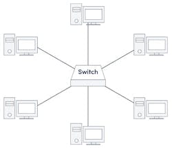
To illustrate this point, let’s look at a basic star topology. Suppose one device in a star network (Fig. 1) wants to send data to another device. In that case, it first sends the info to the connecting network device (i.e., a network switch) at the center of the star, which then transmits the data to the designated device.
The obvious disadvantage of providing multiple paths is if the network switch at the center fails, all attached nodes are disabled, and users at multiple data centers can’t participate in network communication. In fact, a consequence of single-path designs is that any hardware failure, power outage, or cable disconnection will interrupt all types of network communications.
To get around these limitations and improve redundancy, network administrators can add segments or additional industrial switches, or they could use another type of topology altogether, such as mesh, link aggregation, and redundant rings. It’s important to note here that whenever computers share information over a LAN with redundant pathways, looping issues may emerge and bring about broadcast storms.
Broadcast Storm
Broadcast frames can be taken down by flooding the network with bogus frames, therefore preventing important frames from getting on the network or reaching their destination. Two major sources (but not the only) of these types of frames come from either malicious denial-of-service attacks or failing Ethernet devices. Fewer of the latter have occurred in recent years thanks to improved Ethernet device quality. A bad configuration might also cause this issue.
Typically, a broadcast frame is passed through a switch to all ports. It’s a broadcast, as the name says, and it goes to everyone. However, a switch with Broadcast Storm Protection turned on will see too many broadcast frames and squelch them down, preventing them from propagating throughout the network.
Once the broadcast stream has subsided, the switch will permit the traffic to pass once again. It resets itself. This is usually turned on by default in most switches. Some applications may require it to be turned off due to traffic being intentionally broadcast, but it’s very rare.
Spanning Tree Protocols
To break looping cycles and avoid broadcast storms, network administrators have long implemented the Spanning Tree Protocol (STP), a popular layer 2 protocol. STP prevents the occurrence of network loops by blocking all redundant networks' ports. In a loop-free network, a single device with a blocked port will still receive data, but it will not send that data out to other devices on the network.
STP disables links that aren’t a part of the spanning tree, leaving just one primary path and one active channel between any two network nodes. When a network failure does occur, though, devices are able to continue communicating across the network since data can be rerouted around the failure. The port that’s selected depends on the topology of the configuration.
Spanning Tree (STP, RSTP, MSTP)
The STP protocol has three versions: STP (802.1d), Rapid STP (RSTP, 802.1w), and Multiple STP (MSTP, 802.1s). The main advantage of RSTP over STP is its reduction in convergence time. When there’s a topological change, RSTP can usually react in a matter of five to 10 seconds, whereas STP can take up to 50 seconds.
MSTP is the application of STP to a virtual LAN (VLAN). MSTP maps a group of VLANs into a single Multiple Spanning Tree instance. This results in improved network performance and stability by ensuring that only one active path exists between any two nodes in an MST instance. A switched network is divided into multiple regions by MSTP, and each region has multiple independent spanning trees. MSTP not only facilitates rapid network convergence, but it also lets the data flows from different VLANs be routed separately.
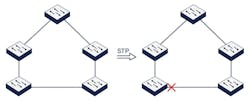
Ethernet networks must not have loops. Spanning Tree Protocols (Fig. 2) prevent loops by disabling one of the connections. If one of the working connections should fail, Spanning Tree will enable the originally disabled link to provide connectivity once again.
RSTP differs from STP in that it uses faster algorithms to block and unblock the links. MSTP works on VLAN connections rather than physical interface connections, which allows it to block data from a single VLAN that’s created a loop while enabling other VLANs that aren’t looped to continue to use the link.
Other Resilience Strategies and Protocols
Beyond STP, RSTP and MSTP, there are several other resilience protocols and technologies. Three worth noting are Ethernet Ring Protection Switching (ERPS), link aggregation, and Virtual Router Redundancy Protocol (VRRP).
Ethernet Ring Protection Switching (ERPS)
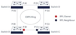
The open standard ITU-T G.8032 Ethernet Ring Protection Switch (ERPS) protocol has a < 50-ms network recovery time standard to create a ring of nodes configured to prevent loop issues. While nodes are arranged in a ring, one connection is always blocked to prevent the creation of a loop. This way, traffic can flow in both directions around the ring but always stops at the blocked link.
If another link in the ring goes down, it becomes the blocked link, and the previously blocked link is opened. As a result, data flow continues at the same rate with virtually no loss of speed.
ERPS rings can also be connected in multiple layers to create larger stacks. Even over hundreds of miles of fiber connections, the protected ring structure of ERPS means that ping won't drop, and connections will remain stable. If you're building out a new network redundancy and framework that prioritizes rapid recovery, ERPS may be the best choice.
Again, Ethernet networks must not have loops. ERPS (Fig. 3), like STP, disables a link to remove the loop from the network. Similar to the Spanning Tree protocols, if a working link should fail, the previously disabled link will be re-enabled, creating a more resilient network.
While STP can be used in a network that looks like a mesh, disabling multiple links to prevent loops, ERPS can only be implemented in a loop. By limiting the design to a loop, ERPS can provide faster healing times (sub 50 ms) to the network.
Link Aggregation
Link aggregation bundles multiple individual Ethernet links together from two or more devices so that the links act as a single logical link. This can be done without using STP to turn off a redundant link. Connecting a switch to another switch, a server, a network-attached storage device, or a multi-port access point are the most typical device combinations.
Besides optimizing load balancing, an important reason for using link aggregation is to provide fast and transparent recovery. An aggregate set of ports is referred to as a link aggregation group (LAG). Each of these links must be the same type of Ethernet (10/200/1000/10G, etc.) and configured identically. The physical links operate in an active-active or active-backup setup, meaning that if one physical link fails, the other can take over and restore the traffic forwarding previously sent over the failed link.
The Link Aggregation Configuration Protocol (LACP) is a point-to-point protocol that creates redundancy and increased bandwidth between devices, typically industrial switches. For example, a loop is created by connecting two Ethernet switches together with two links (Fig. 4).
LACP prevents issues by creating one logical link out of the two links and eliminates the issues caused by a loop. Both links are capable of transmitting different data at the same time, thus doubling the bandwidth. If one link fails, the other can still carry data. Up to eight links can be bound together to form a single LACP connection.
Virtual Router Redundancy Protocol
The Virtual Router Redundancy Protocol (VRRP) is an open standard protocol that enhances network reliability by providing router redundancy for network services. VRRP does this by using physical hardware and creating a virtual router consisting of several physical routers. When packets are delivered to the virtual router from one server's IP address, the industrial router with the highest priority acts as the master. The group's other routers stay in standby mode, prepared to take over if the master router malfunctions.
In an interconnected industrial world, a network outage can be catastrophic. However, many organizations continue to run on outdated technologies, which could impede growth, raise cybersecurity threats, and reduce productivity. Modernizing an industrial network isn’t just about upgrading outdated technology, but also improving resiliency.
>>Download the PDF of this article
About the Author
Henry Martel
Field Application Engineer, Antaira Technologies
Henry Martel is a Field Application Engineer with Antaira Technologies. He has over 10 years of IT experience, along with skills in system administration, network administration, telecommunications, and infrastructure management. He has also been a part of management teams that oversaw the installation of new technologies on public works projects, hospitals, and major retail.


