Why Current Safety Analysis Methods Fail at Covering Lethal System Designs
Download this article in PDF format.
What you’ll learn
- What may have occurred with the Tesla Autopilot System (v2.5) and lane marking.
- The basics behind System-Theoretic Process Analysis (STPA).
- The 4 steps in implementing STPA.
When we look at today's focus of our safety efforts, we see that we mostly deal with the following topics:
- Functional safety
- Safety of the intended functionality (SOTIF)
- Safety in use (SiU)
- Security
- Active/passive safety systems
Functional safety and the ISO 26262 deal with safety-related systems that include one or more E/E systems (electrical and/or electronic) and the corresponding hazards that come from a malfunction of these E/E safety-related systems. Safety of the intended functionality (SOTIF) refers to hazards resulting from functional insufficiencies of the intended functionality.
Safety in use (SiU) tries to cover hazards arising from the interaction of the safety-related system with a human operator. Security is a topic which has significant impact on safety, for example, when a safety-related system isn’t secure against unauthorized access from a third party, who then might be able to manipulate the system. Active and passive safety systems also try to prevent accidents or activate during a collision to protect the driver and passenger, respectively.
Looking at this list, the question arises sooner or later on whether we’re missing something in our combined safety efforts. Something that poses a risk to humans but currently isn’t covered by the safety efforts that we invest.
Tesla Autopilot System (version 2.5)
As an example, let's look at the Tesla autopilot system (version 2.5) and a scenario where this system behaved unsafely. In normal conditions, the autopilot can detect both lane markings of the ego lane and steers the vehicle accordingly to stay at the center of the lane. However, at some point, the system may lose one or both lane markings and is obliged to react accordingly. This can be due to, for example, missing or intermittent lane markings on the road, or the system incorrectly interpreting the given lanes.
In the case of only one detected lane marking, the system is designed to keep working with the remaining lane marking as the only reference for steering the car. Problems may arise when this lane marking leads the ego vehicle into entering a forbidden area, where the vehicle would crash into a barrier ahead:
The takeaway from this scenario is the fact that all technical components performed exactly as designed and tested. There was no component failure. No system was hacked from the inside or the outside that led to a component failure and/or misbehaving components. It wasn’t a problem of SiU since the driver is required to give the control to the autopilot system. Systems of active and passive safety (e.g., seat belts, ABS, ESP, etc.) can’t deal with this kind of issues as well. Regarding SOTIF, even with enough sensor performance for lane marking detection, the problem of incorrect interpretation of sensor data and a resulting false system belief of its environment is normally not part of SOTIF analyses.
There’s a gap in our safety efforts, focusing on the belief of the system about its environment rather than the failure of components. New problems often require a new analysis method to cover these topics, like the System-Theoretic Process Analysis (STPA).
System-Theoretic Process Analysis (STPA)
When dealing with safety, our current procedures trained us to primarily look at component failures. Component failures can lead to unreliable but safe scenarios as well as to unsafe scenarios (Fig. 1).
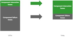
For both cases, the safety community already has very powerful analysis methods at their disposal, e.g. FMEA, FTA, HAZOP, etc. It’s shown that due to our increased skills in performing classic safety analyses such as FMEA and FTA, losses resulting from component failures have decreased significantly over the last decades (Fig. 2).
Losses due to component interaction, though, have increased at the same time. In case of unsafe scenarios that aren’t a result of component failures but of losses, the former mentioned safety analysis methods are no longer sufficient. This is where the method of STPA can complete the toolbox of safety analyses. STPA isn’t meant to replace one or more of the already established methods, but to extend the possibilities of analysis methods to also cover hazards that arise from a non-component failure.
Basics of STPA
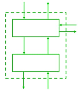
The traditional hazard analysis is based on decomposition. A complex system is broken down into its single components, which in turn and isolation are analyzed for failures. The results are then combined in order to understand the behavior of the composed components. This approach requires that the components are independent of each other.
If this assumption isn’t met, then the decomposition of a system into components and their individual analysis will not reflect the final system behavior. This approach, however, proved very useful for the types of systems that were built a few years ago, and it’s still valid for certain properties of our systems today.
Looking at more recent systems, we see that the increased complexity led to a point where the approach of system decomposition proves no longer sufficient. System decomposition can’t identify behavior that’s not related to individual components, but rather arises from the interaction of those components. In these systems, problems don't arise from component failure—they’re due to component interactions/system designs. System decomposition can’t find these problems.
A new method is needed that closes those gaps. We need to start looking at the system as a whole and not focus on the separate parts/components. System theory does exactly that.
In system theory, a system is regarded as a whole, not as the sum of its parts. System theory deals with emergent properties, which are properties that aren’t the sum of components but emerge when the system components interact.
In 2012, Nancy G. Leveson introduced the System-Theoretic Accident Model and Processes (STAMP)1, which is based on system theory as well as control theory. STAMP provides the theoretical foundation to STPA. In STAMP, “safety is treated as a dynamic control problem rather than a failure prevention problem2.” However, STAMP isn’t an analysis method. It’s a “model or set of assumptions about how accidents occur2.”
STPA is an analysis method based on STAMP. It uses the system-theoretic approach to analyze potential causes of accidents during development so that hazards can be eliminated or controlled.
Overview of the Method
The STPA consists of four consecutive steps (Fig. 3):
- Definition of the purpose of the analysis
- Modeling of the control structure
- Identification of Unsafe Control Actions (UCAs)
- Identification of loss scenarios
Step 1: Definition of the purpose of the analysis
This first step is to identify the system that’s supposed to be analyzed. For this purpose, it’s important to define system boundaries to explicitly state where the system responsibilities end—what is, per definition, the system and what belongs to the environment.
It’s also important to define which kind of losses the analysis shall prevent. Is the focus on traditional safety goals like loss of human life and/or injury of humans, or also, for example, are economic factors a concern?
After the system boundaries are defined, the losses are identified. The definition of a loss reads as follows: "A loss involves something of value to stakeholders. Losses may include a loss of human life or human injury, property damage, environmental pollution, loss of mission, loss of reputation, loss or leak of sensitive information, or any other loss that is unacceptable to the stakeholders2." As the definition states, in the beginning of the analysis, the stakeholders must define which losses they want the analysis to focus on.
Examples of losses for an adaptive-cruise-control (ACC) system include:
- L-1: Loss of life or injury to people
- L-2: Damage to the ego vehicle or objects outside the ego vehicle
- L-3: Loss of mission
- L-4: Loss of customer satisfaction
For the identification of losses, it’s important to note that losses should not reference individual components or specific causes.
Once the stakeholder losses are defined, system-level hazards are identified. The definition of a system-level hazard reads as follows: "A hazard is a system state or set of conditions that, together with a particular set of worst-case environmental conditions, will lead to a loss2."
Whereas losses may include some parts of the environment, over which the system developer has no control, hazards only include parts of the system inside the system boundary, over which the system developer has control. Control is necessary since it’s the hazards that we’re trying to eliminate (or at least mitigate) by the design. System-level hazards identify "system states or conditions that will lead to a loss in worst-case environmental conditions2."
When defining hazards, it’s crucial that hazards not be confused with causes of hazards. Therefore, it’s again important that hazards don't refer to individual components of the system. The format of describing a hazard should be:
“< Hazard > = < System > & < Unsafe condition > & < Link to losses >”2Hazards also need to fulfill three criteria:
- "Hazards are system states or conditions (not component-level causes or environmental states)
- Hazards will lead to a loss in some worst-case environment
- Hazards must describe states or conditions to be prevented"2
Examples for hazards for an ACC system include:
- H-1: Ego vehicle does not maintain safe distance from traffic participants or objects [L-1, L-2, L-3, L-4]
- H-2: Ego vehicle enters dangerous area outside of the operational design domain [L-1, L-2]
- H-3: Ego vehicle exceeds safe operating envelope for the environment [L-1, L-2, L-4]
Note the traces to the losses in the brackets behind the hazards.
In the final action of step 1, system-level safety constraints are derived. The definition of a system-level safety constraint is: "A system-level constraint specifies system conditions or behaviors that need to be satisfied to prevent hazards (and ultimately prevent losses)2."
System-level safety constraints can be derived by simply inverting the condition of the system-level hazard:
“< Safety constraint > = < System > & < Condition to enforce > & < Link to hazards >”2, or as a rule of thumb:
“< Safety constraint > = If < hazard > occurs, then < what needs to be done to prevent or minimize a loss >”2
What we will look at in steps 2 to 4 is a systematic identification of scenarios that can violate these system-level safety constraints.
Step 2: Modeling of the control structure
Step 2 models the corresponding control structure (Fig. 4).
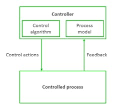
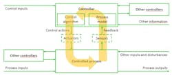
The definition of the control structure reads as follows: "A hierarchical control structure is a system model that is composed of feedback control loops. An effective control structure will enforce constraints on the behavior of the overall system2." The control structure is composed of control loops (Fig. 5). The controller provides control actions to control the process of interest and its behavior. The control algorithm represents the decision-making process of the system. It’s the active part of the controller. The process model represents the knowledge of the system, the so-called belief of the system about its environment and system state. The controller builds its process model—its internal belief of the environment, based on feedback from the controlled system.
Problems can arise anywhere in the control loop. The belief of the system in the process model could be wrong. Control actions performed by the control algorithm might be unsafe in a specific situation. Feedback could be missing or incorrect.
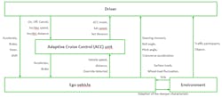
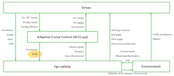
When this control loop is applied to real systems, most systems consist of several nested control loops; Figure 6 illustrates a basic control structure of an ACC example. It consists of five control loops (driver – ACC unit; ACC unit – ego vehicle; driver – ego vehicle; ego vehicle – environment; driver – environment).
When a control structure is developed, it must be analyzed to determine who or which part of the system acts as a controller over which process. After identifying the controller and controlled process, the control actions are derived. Every action that the controller can execute on the controlled process is a control action and is introduced into the control structure model. In the same way, every feedback that is sent/given from the controlled process to the controller is modeled in the control structure in the same way (Fig. 6, again).
It’s important to note that as a possible point of confusion, a control structure isn’t a physical model—it’s a functional model. This way it’s possible to also display interactions that aren’t physical in nature; for example, the communication between a flight crew and an air traffic controller.
Step 3: Identification of Unsafe Control Actions (UCAs)
Step 3 identifies the unsafe control actions. Every control action that was identified in the control structure in Figure 6 is analyzed to determine whether this control action can be unsafe in a certain scenario. For this analysis, a guide-word-driven approach is used, such as in a HAZOP analysis. For an exemplary analysis, we look at the brake command executed from the ACC system on the ego vehicle (Fig. 7).
The guide words often used for the analysis are:
- Not providing causes hazard
- Providing causes hazard
- Too early, too late, out of order
- Stopped too soon, applied too long
These guide words can be adapted or changed. However, John P. Thomas often says, "these guide words cover all possible cases." From our experience, in most cases, an adaption of the guide words isn’t necessary because this preset of guide words is usually sufficient for the analysis. The guide words are then applied to every control action to see whether in a certain scenario this control action can be unsafe (Fig. 8).
Every identified UCA is then linked to a hazard for traceability. After identifying UCAs, controller constraints can be derived to avoid the unsafe control action. In general, UCAs can be inverted so as to directly result in controller constraints, which are defined as: "A controller constraint specifies the controller behaviors that need to be satisfied to prevent UCAs.2" One example is the brake control action (Fig. 9).
Step 4: Identification of Loss Scenarios
The last step of the STPA focuses on the identification of loss scenarios. Here, the whole control loop is analyzed for causal factors (Fig. 10).
Two types of loss scenarios need to be considered:
- Why would unsafe control actions occur (upward arrow in Figure 10)?
- Why would control actions be improperly executed or not executed (downward arrow in Figure 10)?
Why would unsafe control actions occur?
To determine how unsafe control actions may occur, the path of the UCA can be walked backwards. We analyze for each UCA what could have led to the unsafe control action. There are a few possibilities that can lead to UCAs:
Unsafe controller behavior:
- Failures related to the controller. Example: physical failure of the controller (power loss, etc.)
- Inadequate control algorithm. Example: a flawed implementation, the algorithm itself could be flawed, etc.
- Unsafe control input. Output from other controllers could be unsafe, leading the controller of the control structure to an unsafe behavior, too.
- Inadequate process model. Process models represent the internal belief of the controller about its environment. Flaws in the process model occur when the controller's belief does not match reality. This can be based on incorrect feedback, incorrect interpretation of feedback, unavailable feedback, etc.
Inadequate feedback and information:
- Feedback or information not received. Example: feedback that’s sent but not received, feedback isn’t sent, etc.
- Inadequate feedback received. Example: sensor feedback that’s inadequate, sensors that aren’t able or designed to provide needed feedback, etc.
Why would control actions be improperly executed or not executed?
Hazards can also arise without having UCAs, but with having correct control actions not executed or improperly executed. Possibilities for this to happen include:
Scenarios involving the control path:
- Control action not executed. Example: a control action is sent but not received, actuator doesn’t respond, etc.
- Control action improperly executed. Example: a control action was received correctly but was responded to inadequately, control action isn’t sent but actuators behave as if it had been sent.
Scenarios related to the controlled process:
- Control action not executed. Example: if the control action was properly received, but the controlled process doesn’t respond.
- Control action improperly executed. Example: if the control action was properly received, but the controlled process responds inadequately.
Conclusion
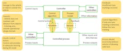
If we now apply the introduced steps to our initial Tesla autopilot system (version 2.5) example, how could this have helped us to identify the problem? Figure 11 shows the steps of the STPA that could have led to the identification of the system behavior of entering an area outside the operational design domain.
The identified loss could have been, for example, "Damage to the ego vehicle or objects outside the vehicle." Corresponding hazards could have been, say, "Vehicle does not maintain safe distance from objects" and "Entering area outside operational design domain." An unsafe control action could have been, for example, "Control unit provides in-adequate steering during AD mode." The feedback to the controller could have been, for example, "Insufficient lane markings received." The control algorithm itself is implemented as "If only one lane marking is detected, follow this lane marking.” This would be hazardous in the combination with the internal system belief in the process model "Incorrectly believes vehicle is following valid lane."
We see that by applying the STPA on a system level, even without further technical knowledge of the system, potentially hazardous scenarios can already be identified and requirements for their mitigation or even elimination can be derived.
Simon Friedmann is Functional Safety Consultant and Julian Ott is Safety Engineer at Elektrobit.
References
1. Nancy G. Leveson, Engineering a Safer World, MIT Press, 2012.
2. Nancy G. Leveson, John P. Thomas, STPA Handbook, 2018.


