Battery-Monitoring ASICs Boost EV Range and Safety
Download this article in PDF format.
As vehicle electrification progresses, engineers must take care to maximize battery life while ensuring the highest levels of functional safety. Battery-monitoring application-specific integrated circuits (ASICs) can assist with both aims, implementing an automatic host-reverse-wakeup function, monitoring cell voltage and temperature, and providing autonomous cell balancing.
Sponsored Resources:
- Conserve battery power in HEV/EVs with industry's first patented automatic host reverse wakeup
- Functional safety considerations in battery management for vehicle electrification
- Enhance thermal management in EVs with autonomous cell balancing
Functional Safety
Electric-vehicle safety considerations are multifaceted. They include protecting production workers, owners, mechanics, and recyclers from high voltages; protecting battery cells from puncture and impact damage; and maintaining the integrity of the electrical system that ensures the cells operate within safe temperature and voltage ranges.
This last consideration is of particular importance. Outside of acceptable voltage and temperature ranges, undesirable reactions may occur within the battery that can lead to excessive self-heating, internal electrical shorts, and ultimately cascading thermal runaway. To avoid these issues, battery-monitoring ASICs measure and transmit information about voltage and temperature to a battery-management unit (BMU).
The battery-management function faces its own challenges. An electric passenger vehicle may have 128 or more cells; a commercial vehicle may have twice that number. Large battery systems have many printed-circuit-board (PCB) connections where faults can occur: opens between a cell sensor and an ASIC, for example, or opens in the communications links between ASICs. Detecting and addressing such faults to avoid hazardous events is part of functional safety, as addressed in the ISO 26262 standards for road vehicles.
In some automotive systems, the safe response to a loss of functionality is simply to switch off the electronics and notify the driver through a dashboard indicator. In other cases, however, simply switching off the electronics may not be safe, and design goals may include a “safety-related availability” requirement in which the system must have a tolerance—perhaps achieved through redundancy—for some types of faults for a period of time to avoid hazardous events.
A battery-monitoring subsystem provides examples of how redundancy might work. In such a subsystem, ASICs are arranged in a stacked configuration, with each measuring voltage and temperature of multiple cells. Measurement data streams from ASIC to ASIC and to a microcontroller unit (MCU), which calculates the state of the battery and helps ensure that operation remains within a safe range. Opens or shorts in the sensing or communications paths could “blind” the subsystem to potential faults, possibly leading to a hazardous event.
Texas Instruments’ BQ79606A-Q1 and BQ79616-Q1 families of battery-monitoring ASICs include features that provide tolerance for these types of faults, enabling the system to continue monitoring battery-pack health and safety.
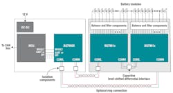
Figure 1 illustrates BQ79616-Q1 devices in a bidirectional ring configuration. In the event of an open between two battery-monitoring ASICs, the MCU continues to communicate with the ASICs by way of a BQ79600-Q1 SPI/UART communication interface, switching the direction of messaging backward or forward as necessary. Although normal communication is disabled during a fault, the system can maintain availability using the fault tolerance of the bidirectional ring communication feature—with no loss of voltage and temperature information from the battery modules.
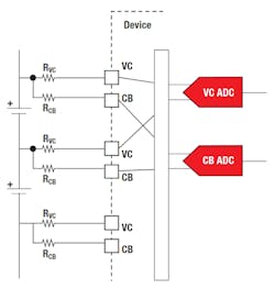
Further supporting redundancy, the BQ79606A-Q1 and BQ79616-Q1 also feature dual analog-to-digital converters (ADCs). In a system without redundancy, a single ADC monitors the voltage sensing signal (VC). With the dual ADCs of the BQ79606A-Q1 and BQ79616-Q1, a second ADC monitors the cell-balance signal (CB), thereby allowing the system to continue monitoring voltage even if an open occurs in the VC path (Fig. 2).
Automatic Wakeup
A typical electric or hybrid-electric vehicle includes a BMU powered by a 12-V battery. To look for faults in the high-voltage (HV) battery pack when the vehicle is parked, the BMU’s MCU periodically must wake up, potentially prematurely discharging the 12-V battery.
An alternative is an automatic host-reverse-wakeup implementation that wakes up the MCU only on detection of a fault. The BQ79616-Q1, which incorporates a patented wake-up-at-fault feature, can serve at the heart of such an implementation. The BQ79616-Q1 offers a low-power sleep mode during which it can still monitor overtemperature and undertemperature, as well as overvoltage and undervoltage, fault conditions. On detecting a fault in sleep mode, the device is able to transmit the fault status through a fault tone.
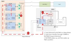
As shown in Figure 3, a series of BQ79616-Q1 devices monitor the HV batteries. On detecting a fault, a BQ79616-Q1 transfers, via a ring architecture, the fault tone to a BQ79600-Q1 communication interface located on the BMU. The BQ79600-Q1 then enables the BMU’s power-management IC (PMIC), which in turn wakes up the MCU. The result is conservation of 12-V battery power while supporting functional safety requirements while the vehicle is parked or turned off.
Cell Balancing
Cell balancing can correct imbalances in a vehicle’s battery and help extend vehicle driving ranges while ensuring safe operation. You can choose one of two approaches. Active cell balancing employs dc-dc converters to redistribute energy from a cell with a high level of charge to one with a lower level. Passive balancing removes charge from cells with more charge, typically through thermal dissipation, until all cells have the same amount of charge. Passive balancing is a more popular approach given its simplicity and lower cost.
TI’s BQ79616-Q1 performs passive cell balancing using internal switches that connect to external balancing resistors. Both of the switches within the device and the resistors are potential sources of overheating, which the BQ79616-Q1 addresses with two thermal-management functions.
With the first, a high die temperature triggers a fault to the MCU, which pauses balancing until the die temperature drops and any fault is cleared. With the second, the BQ79616-Q1 monitors circuit-board-mounted thermistors and automatically pauses balancing if temperature exceeds a preset threshold. Balancing resumes when the temperature drops to an acceptable level—all without intervention of the MCU.
Conclusion
TI’s battery monitors and balancers perform a variety of functions in electric vehicles, from wake-up-on-fault operation to cell balancing. They offer thermal-management features and implement fault-tolerant temperature and voltage measurement, providing systematic functional safety capability up to Automotive Safety Integrity Level (ASIL) D.
Sponsored Resources:


