EV Charging Station Innovations Boost Efficiency and Speed
Members can download this article in PDF format.
The proliferation of electric vehicles is driving the need for a charging infrastructure, and it must include electric-vehicle supply equipment (EVSE) that’s both energy-efficient and fast. Although overnight charging may be acceptable for some commuters, most drivers will demand the flexibility that comes from half-hour charging operations.
Sponsored Resources:
- How to select the right power topology for your EV charging station design
- Spend less than 30 minutes at an EV charging station
- How to design a fast, portable EV charger
Power Topologies
Charging systems come in two basic types—ac and dc—and three levels (L1, L2, and L3). An ac charger supplies ac voltage to an EV’s onboard charger (OBC), which incorporates an ac-dc converter as shown in Figure 1. An L1 ac implementation operates at 120 or 230 V ac (single phase) and can charge a 24-kWh battery in approximately 17 hours. An L2 implementation operates at 208 to 240 V ac (single/split phase) and can charge the same battery in approximately eight hours.
In contrast, an L3 dc charger operates on polyphase voltages and bypasses the EV’s OBC to deliver dc charge directly to the vehicle battery (Fig. 2). An L3 dc implementation can bring a 24-kWh battery to an 80% state of charge (SOC) in less than 30 minutes. Modular power converters incorporated in dc chargers can be paralleled to support different power levels. Key parameters for dc chargers include energy density and energy efficiency, both of which are enabled by high switching frequencies. High frequencies minimize the size of a charger’s magnetics and minimize losses, allowing for the use of smaller heatsinks.
Both ac-dc and dc-dc power stages are included in dc charging stations. The ac-dc stage converts grid voltage to a dc link voltage of approximately 800 V. This stage also is called the power-factor-correction (PFC) stage; it maintains sinusoidal input currents with THD typically less than 5%. The dc-dc stage converts the dc link voltage to the voltage required for a specific vehicle’s battery.
You can implement dc charger stages using several topologies. The ac-dc PFC topologies include the single-phase totem-pole topology—a conventional boost PFC topology with one half of the diode bridge replaced by active switches in a half-bridge configuration. The Vienna rectifier power topology serves high-power, three-phase PFC correction applications and offers continuous-conduction-mode (CCM) operation, inherent multilevel switching, and reduced voltage stress on the power devices. And the three-phase active neutral-point-clamped (ANPC) converter topology offers benefits such as high power density, low switching losses, and high efficiency.
Topologies for the dc-dc stage include the LLC resonant converter, whose gain is a function of switching bridge gain, resonant tank gain, and transformer turns ratio. This converter generally is used in applications less than 5 kW. Another dc-dc topology is the dual-active-bridge (DAB) converter, which consists of a full bridge with active switches on both the primary and secondary sides connected by a high-frequency transformer.
V2G and Portable Chargers
Converter topologies including the ANPC and DAB can operate in bidirectional mode. Bidirectionality is a key feature for supporting vehicle-to-grid (V2G) applications now being addressed by the automotive industry, in which a car battery can provide load balancing by feeding power back to the grid at times of peak demand.
In addition to pursuing V2G applications, the industry also is investigating the use of portable dc chargers, which could eliminate the need for the onboard ac-dc chargers in today’s EVs. The portable chargers would likely employ natural convection-based cooling, possibly requiring their manufacturers to look at GaN- or SiC-based architectures operating at frequencies ranging from hundreds of kilohertz to a few megahertz.
The portable chargers could offer several benefits. You could select a portable charger rating that best matches your daily driving routine and the time you have available for a charging cycle. Since the charger would reside outside the vehicle, it might not require expensive AEC-Q100 automotive-qualified components, thereby reducing overall system costs. In addition, eliminating the weight of the onboard charger can increase EV range (although you may need to take the portable charger with you depending on charging infrastructure available at your destination). Finally, your portable charger could be repaired with no downtime for your EV.
Products and Reference Designs
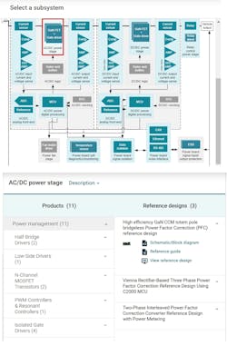
To help you get started with your EV charger design, Texas Instruments offers an interactive block-diagram tool, which points you toward relevant products and reference designs for subsystems ranging from the ac-dc analog front end to the relay-control power stage. Figure 3 shows the ac-dc power stage selected. Products include half-bridge drivers, low-side drivers, N-channel MOSFETs, and pulse-width-modulated (PWM) controllers. The tool also highlights a GaN totem-pole bridgeless, three-phase Vienna-rectifier-based reference design and a two-phase interleaved PFC reference design.
If you highlight the dc-dc power stage, the tool will point you to, among others, a bidirectional dual-active-bridge reference design for L3 EV charging stations. The reference design implements a dc-dc converter using a single-phase DAB topology, which offers soft-switching commutation and high efficiency. The modular, symmetrical DAB structure makes it possible to stack converters to achieve high power.
This reference design includes three main intercommunicating sections: a power board with silicon-carbide (SiC) MOSFETs, a high-frequency transformer, and isolated current- and voltage-sensing electronics; four gate driver cards, each having a UCC21530 isolated dual-channel gate driver to drive the SiC MOSFETs in the half-bridge configuration; and a TMDSCNCD280049C digital control card. The reference design supports a primary voltage of 700 to 800 V dc and a secondary voltage of 380 to 500 V dc with a maximum power output of 10 kW. Full-load efficiency is 97.6%, peak efficiency is 98.2% at 6 kW, and power density is 1.92 kW/l.
Conclusion
L3 dc chargers can bring an EV battery to 80% SOC in less than 30 minutes. Bidirectional implementations enable V2G applications, while portable dc chargers promise new levels of flexibility. Online tools can speed your design of a charger’s various stages. And finally, a bidirectional DAB reference design addresses EV-charging and energy-storage applications where power density, cost, weight, galvanic isolation, high voltage conversion ratio, and reliability are critical.
Sponsored Resources:


