All EVs employ rechargeable batteries, so proper care of these batteries is critical to operation of the vehicle. To see how they impact vehicle design and the electrical grid, we have to look at the characteristics of these batteries, which are usually li-ion.
EV battery packs are made up of multiple cell modules arranged in series and in parallel. The battery pack has a battery management system (BMS) that monitors components close to the battery cells themselves. During the charging and discharging of an EV battery, each cell within the battery pack must be closely and accurately monitored, because unbalanced cell voltage conditions can impact battery performance.
Intelligent battery management and charging of the battery is necessary to protect the safety of the vehicle’s occupants since EV batteries are typically several hundred volts. Over-voltage or under-voltage conditions can cause a battery failure that affects vehicle operation.
Charging EV batteries could pose a challenge to the nation’s electricity grid as more EVs appear on the roads. Eventually, uncontrolled charging of EVs at maximum power might require substantial, costly investments in the nation’s electricity system. And, enlarging a utility to meet increased peak demands could lead to excess generating capacity that will sit idle much of the day.
The answer to the variable grid loading situation is smart chargers, which control their demand depending on grid loads and the vehicle owner’s needs. This gets complicated because grid loads are variable. For example, small appliances are turned on and off frequently so they use larger amounts of power for a few minutes. Air conditioners automatically cycle on and off to maintain the proper temperature, at times resulting in very large swings in power demand.
Therefore, a Smart Charger must shift battery charging loads to run when there is less power demand on the grid. This requires the EV to send the vehicle’s battery state-of-charge to the utility. Without it, vehicle owners face the risk of not charging the battery properly.
Smart charging has to be tailored to the types of charging stations that vary in their location and usage:
- Typically, for a residential charging station, the EV owner plugs in when returning home, allowing the car to recharge overnight. A home charging station usually has no user authentication or metering, and may require wiring a dedicated circuit.
- Charging in public charging stations may be slow or high speed and encourages EV owners to recharge their cars while they take advantage of nearby facilities.
- To allow for longer-distance trips, there may be fast charging at public charging stations >40 kW.
Public charging stations may be networked—that is, several are linked together at multiple locations, and the utility receives information from all of them. These networked EV charging systems require “intelligent charging solutions,” where chargers are linked seamlessly with the grid and charging system operators.
Tesla supercharging stations charge with up to 145 kW of power distributed between two adjacent cars, with a maximum of 120 kW per car. That is up to 16 times as fast as public charging stations; they take about 20 minutes to charge to 50%, 40 minutes to charge to 80%, and 75 minutes to 100%. The charging stations provide high-power DC charging power directly to the battery, bypassing any internal charging power supply. The next version of Tesla Supercharging is expected to charge with more than 350 kW.
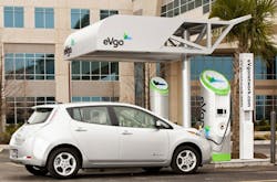
Electric vehicles at public stations could charge their batteries with lower current during peak power demand. Figure 1 shows a Nissan Leaf being recharged with an eVgo public charging station.
To aid the control of power required from the grid:
- Smart chargers should adjust their charging rate to accommodate variations in grid power demand.
- The electric grid should see a gradual “ramp” from the mid-day load to the evening peak.
Battery Management
Electric vehicles employ battery management systems that work in real time to monitor the performance of individual battery cells. That is, each cell must be monitored to ensure it is operating properly and that there is balanced cell load sharing. Besides managing battery operation, the BMS often has to handle other vehicle functions, including the vehicle’s desired operating mode—whether it is accelerating, braking, idling, or stopped—which can then activate appropriate power management functions.
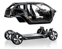
An example of one form of battery management is employed in the BMW i3 concept car, which positions its li-ion batteries between the front and rear axles and the drive module on top of the battery pack (Fig. 2). This electric vehicle manages batteries by monitoring individual battery cell performance connected to a central BMS master via cables and wiring harnesses. An LTC6811from Linear Technology manages battery conditions with the help of a wireless BMS. It supplies individual battery cell performance feedback via wireless RF communication. Among its benefits, this wireless BMS:
- Eliminates maintenance prone connectors, cables, and harnesses.
- Permits the addition of new sensors to improve reliability.
- Simplifies vehicle assembly and battery maintenance.
- Provides designers with additional mechanical design flexibility.
- Allows precise timestamped data collection that can improve battery condition feedback.
Checking individual battery cells is a critical concern for EV batteries. Among the safety concerns are thermal runaways that could cause a fire in the vehicle’s battery. Thermal runaways can be due to several malfunctions, such as overcharging. To help avoid unsafe events, the BMS must be able to constantly monitor and detect changing operating parameters and take protective action, like shutting down a battery cell that is overheating.
Another safety concern is the ability to verify that alarms/alerts are genuine and not a failure in the BMS. Plus, the BMS must have built-in protection functionality that can instantaneously take the proper and most effective action to head off a runaway condition before it potentially becomes unsafe.
Standards
Related to battery charging is the SAE J1772 (IEC Type 1), a North American standard for electrical connectors for electric vehicles maintained by SAE International. Its formal title is SAE Surface Vehicle Recommended Practice J1772, SAE Electric Vehicle Conductive Charge Coupler. It covers the general physical, electrical, communication protocol, and performance requirements for the electric vehicle conductive charge system and coupler. The intent is to define a common electric vehicle conductive charging system architecture that includes operational requirements and the functional and dimensional requirements for the vehicle inlet and mating connector.
The SAE J1772 standard designates 240 volt AC charging (known as Level 2 charging) and 500 V DC high-current charging (known as DC Fast Charge). Vehicle owners can install a level 2 charging station at home, whereas businesses and local government provide level 2 and DC Fast Charge public charging stations that supply electricity either for a fee or free.
IEC 62196 also covers battery charging:
- Mode 1 – slow charging from a regular electrical socket (single- or three-phase)
- Mode 2 – slow charging from a regular socket, but with some EV specific protection arrangement (i.e., the Park & Charge or the PARVE systems)
- Mode 3 – slow or fast charging using a specific EV multi-pin socket with control and protection functions (i.e., SAE J1772 and IEC 62196)
- Mode 4 – fast charging using some special charger technology such as CHAdeMO
There are three connection cases:
- Case A is any charger connected to the mains (the mains supply cable is usually attached to the charger) usually associated with modes 1 or 2.
- Case B is an on-board vehicle charger with a mains supply cable which can be detached from both the supply and the vehicle—usually mode 3.
- Case C is a dedicated charging station with DC supply to the vehicle. The mains supply cable may be permanently attached to the charge-station such as in mode 4.
There are four plug types:
- Type 1 – single-phase vehicle coupler, reflecting the SAE J1772/2009 automotive plug specifications
- Type 2 – single- and three-phase vehicle coupler, reflecting the VDE-AR-E 2623-2-2 plug specifications
- Type 3 – single- and three-phase vehicle coupler equipped with safety shutters, reflecting the EV Plug Alliance proposal
- Type 4 – fast charge coupler, for special systems such as CHAdeMO
Residential Charging
In the home, the vehicle is connected to the power grid through standard socket-outlets, which depending on the country are usually rated at around 10 A. To use mode 1, the electrical installation must comply with the safety regulations and must have a grounding system, a circuit breaker to protect against overload, and ground leakage protection. The sockets have blanking devices to prevent accidental contacts.
Some EVs have external battery chargers, whereas others are on-board chargers buried within the car. These built-in chargers accept AC power from the home and recharge the car’s battery. These internal battery chargers use a wall-mounted box that supplies 240 VAC to the car’s charger. That box, cord, and plug is the Electric Vehicle Service Equipment (EVSE). A 30 A (AC) EVSE will need a circuit breaker rated for at least 40 A.
An EVSE should handle at least 30 A. One rule of thumb is that a 30 A service will provide the ability to add about 30 miles of range in an hour. In contrast, 15 A will add only about 15 miles in an hour of charging. A cable from the wall-mounted EVSE to the automobile usually runs about 15 to 25 ft.
There are some risks to avoid:
- The socket and cables can overheat following intensive use for several hours at or near the maximum power (which varies from 8 to 16 A depending on the country).
- There are fire or electric injury risks if the electrical installation is obsolete or if certain protective features are absent.
- Exceeding the overall power consumption in the home is another problem. The home’s charging socket shares a feeder from the switchboard with other sockets (no dedicated circuit). If the sum of all consumptions exceeds the protection limit (in general, 16 A), the circuit-breaker will trip, stopping the charging.
All these factors impose a limit on the power in mode 1, for safety and service quality reasons. This limit is currently being defined, and the value of 10 A appears to be the best compromise.
Charging Connectors
Every EV needs a power connector intended specifically for that vehicle, and there are several different types.
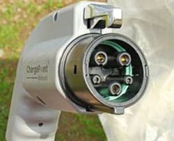
The Japanese-developed CHAdeMO standard was initially favored by Nissan, Mitsubishi, and Toyota, while the (SAE) J1772 combo standard was backed by FCA, GM, Ford, Volkswagen, and BMW (Fig. 3). Now, CHAdeMO (Fig. 4) is an IEEE and an IEC standard.
Both charging systems are direct-current quick-charging types designed to charge the battery of an electric vehicle to 80 percent in approximately 20 minutes, but the two systems are completely incompatible.
The Combined Charging System (CCS) is a quick charging method that delivers high-voltage direct current via a special electrical connector derived from the SAE J1772 (IEC Type 1) or IEC Type 2 connector (Fig. 5). It is a combination of an AC connector with a DC option.
Automobile manufactures that support CCS include: Volkswagen, General Motors, BMW, Daimler, Ford, FCA, Tesla, and Hyundai. The CharIN consortium that controls the CCS standard is working on a charging rate of 350 kW beginning in 2017. Competing standards include CHAdeMO and Tesla Supercharger.
Virtually every U.S. and German carmaker has signed on to using the CCS—so named because its connector combines pins for both AC and DC charging. The only cars equipped for CCS that have gone on sale in North America thus far are the BMW i3, Chevrolet Spark EV, and Volkswagen e-Golf.
Tesla Motors has its own Supercharger fast-charging standard. It’s compatible only with the Model S electric car, although its owners can buy an adapter that allows their cars to fast-charge at CHAdeMO stations.


