Stabilize Automotive Power Systems with Silicon Solutions
Download this article in PDF format.
The power system in an automobile is limited and tricky. It’s limited because its primary source is a single 12-V battery that’s regularly recharged. On top of that, the amount of electrical and electronic equipment being added to automobiles increases daily. The new loads include expanded infotainment systems, advanced driver-assistance systems (ADAS), and more sophisticated LED lighting. Other systems that reduce emissions are in the mix, too. But that’s not all. The new electronic additions increase the electromagnetic-interference (EMI) level in the vehicle unless mitigating measures are taken.
As it turns out, there are solutions for all of these design challenges, if you look in the right place. For example, Texas Instruments (TI) offers an array of devices that can accelerate and simplify designs.
Sponsored Resources:
- 4 Channel Antenna LDO Reference Design with Digital Diagnostics and Integrated Protection
- How to minimize undershoot when the pre-boost converter wakes up
- Automotive Start-stop solution for ADAS, infotainment, and cluster applications
LDOs for Remote Supplies
Virtually all new electronic systems in vehicles require a constant stable dc supply voltage. And those sources need to be protected against shorts, opens, overvoltage conditions, and transients. The 12-V battery supply varies widely with constantly changing load conditions and ambient variations in a harsh environment.
As a result, voltage regulation for the loads is essential, and that regulation must not contribute to the EMI/EMC issues in the vehicle. That’s why low-dropout (LDO) regulators are the choice for most automotive loads—they’re efficient and produce no switching noise.
The infotainment and ADAS equipment often requires a remote or “phantom” dc supply. Power is typically delivered over a signal-carrying coax cable that’s subject to shorts, opens, environment degradation, and other maladies. Examples of remote loads include radio/GPS antennas with internal LNAs, backup cameras, and microphones with integral preamp. LDOs for these remote loads are ideal, but protection must be provided.
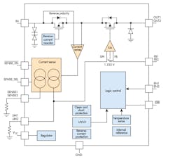
1. Shown is a functional block diagram of the TPS7B770x-Q1 LDO for severe automotive applications. The dc output at OUT1/OUT2 is supplied to the load by a coax cable that also carries the antenna signal. (Courtesy of Texas Instruments)
One solution is a chip like the TI TPS7B7702-Q1, a dual-channel antenna LDO with current sense (Fig. 1). It can handle a wide range of input voltages from 4.5 to 40 V with load dump protection. The output voltage is adjustable from 1.5 to 20 V with a current capability up to 300 mA per channel. A notable feature is the current-sense capability that’s adjustable with an external resistor. The current-sense outputs may be multiplexed between channels and devices to minimize the need for multiple ADCs. The device is usually controlled by a companion MCU.
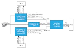
TI also offers a four-channel antenna LDO reference design with digital diagnostics and integrated protection. Designated the TIDA-01569, this reference design demonstrates an approach for powering remote, off-board loads, often over coaxial cables (Fig. 2).
2. The TIDA-01569 reference design implements a common application using the TPS7B7702-Q1 LDO showing two two-channel devices covering four loads. Note the multiplexing of sense lines to the ADC and the MCU control of each device. (Courtesy of Texas Instruments)
This design offers protection against a variety of faults to which off-board cabling is susceptible, along with digital diagnostics. The I2C and fault flag protect against and diagnose reverse polarity, reverse current, short-to-battery, short-to-ground, and thermal shutdown. The integrated reverse-current protection doesn’t require an external diode at the output of the device, which saves cost and avoids increasing the dropout voltage.
Pre-Boost Converters Minimize Battery-Voltage Drops
Another common automotive power problem is the severe drop in battery voltage that occurs during some operations in the vehicle. For example, there’s a serious drop when the engine is starting.
Many vehicles today feature a start-stop system that turns off the engine while stopped and idling. This helps reduce emissions and improve gas mileage. When the vehicle restarts, the battery voltage drops significantly. To help maintain voltages to critical loads during restarting, most vehicles now use pre-boost converters.
The basic requirements of a pre-boost converter are:
- Ability to tolerate an input voltage range between 2.5 and 40 V, 12 V typical.
- Output voltage capability in the range between 8.5 and 40 V.
- Output current in the 2- to 4-A range.
- Short wakeup delay.
One device that more than meets the minimum requirements is the TI LM5150-Q1 boost controller. It can handle an input voltage of 1.5 to 42 V and consumes less than 15 µA of quiescent standby current (IQ). And it offers four selectable output voltages of 6.8, 7.5, 8.5 and 10.5 V.
The device is a switching converter whose switching frequency can be set to any value in the 220-kHz to 2.3-MHz range. A frequency of 2.2 MHz is common, as it helps minimize AM radio interference.
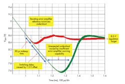
3. Not all pre-boost converters can accommodate the deep voltage drop and undershoot (green curve) that occurs in automotive systems. The TI LM5150-Q1 essentially solves this problem (red curve). (Courtesy of Texas Instruments)
One of the problems that appears with some pre-boost converters is undershoot when the battery voltage drops. Undershoot is a severe multi-voltage decrease in battery voltage that occurs because the pre-boost converter doesn’t wake up fast enough. Figure 3 shows an example. This undershoot can last hundreds of microseconds before the output stabilizes at its set output.
This problem is essentially eliminated by a fast wakeup time and boosting the converter error-amplifier reference voltage. The TI LM5150-Q1 takes care of this problem.
A Reference Design for Automotive Start-Stop Problem
The TIDT001 reference design provides a combined solution to the wide potential voltage drops that can negatively affect demanding automotive infotainment, instrumental clusters, and ADAS equipment. It features the low IQ LM5150-Q1 boost controller and the LM5141-Q1 buck controller that offer features 2.2-MHz switching, few external components, small solution size, and fast dynamic response even under severe start-stop cranking scenarios.
Sponsored Resources:


