Emissions Mission: Integrate 48-V Systems in Mild Hybrids
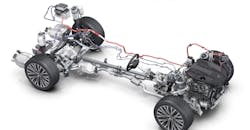
In a typical vehicle, the tractive power systems must be able to operate over a very wide range of power and speed conditions. This is typically referred to in terms of a torque-speed range. Use of the hybridized powertrain gives system designers the freedom to arrange the multiple power sources in ways that optimize each system’s performance during different parts of the torque-speed range.
The electrical power source is able to provide a very large amount of torque, and works well when accelerating the vehicle, but it’s only available for limited amounts of time. The specific time involved depends on both the size of the battery and the torque output of the electrical machine.
With the availability of this high-torque-producing power source, the internal combustion engine (ICE) can be significantly downsized, making it considerably more fuel-efficient. However, adding the electrical power source is certainly no trivial engineering matter and requires an approach that includes design considerations relating to many vehicle systems.
Traditionally, electrification has been achieved by adding a high-voltage (~350 V) battery and a high-performance electric machine directly coupled to the ICE powertrain. These “full” hybrid vehicles have been the defining class of fuel-efficient vehicles and are very attractive from an increased efficiency standpoint. However, they add a considerable amount of cost and weight to the vehicle.
Recently, the 48-V vehicle system architecture has received a considerable amount of attention. These systems can be thought of as a partial step toward a full-hybrid vehicle. Typically, they’re referred to as “mild hybrids,” but when designed at lower power levels can also be categorized as “micro hybrids.” They’re constructed using a relatively compact 48-V battery, a high-performance electric machine, and usually at least one additional 48-V electrified subsystem. The lower cost of 48-V systems is making them an attractive addition to many automotive OEMs, and they may soon be a part of most vehicle manufacturers’ portfolios.
The 48-V Architecture
The choice of 48-V architectures is large and constantly increasing. The most basic system includes a battery, a starter-generator, a 48-V to 12-V converter, and typically at least one 48-V load. Since 48-V vehicles still retain the 12-V battery and multiple 12-V loads, it’s likely that these systems will exist as dual-voltage systems for the present time (Fig. 1).
1. A typical 48-V mild-hybrid system electrical topology has a bidirectional converter that links to the two sides.
With these dual-voltage systems, a plethora of new configurations are possible. Since the 48-V system is fundamentally capable of sourcing higher power levels, it will enable new higher-powered peripherals, like the 48-V E-Turbo and 48-V E-Roll stabilization systems. Also, the higher power availability will encourage power-hungry 12-V loads to migrate to the 48-V bus to take advantage of the higher efficiencies.
Initially, the 12-V system side of the dual-voltage system will remain as is, minus the 12-V alternator. Since there will be no generating source of 12-V power, the need arises for a converter that’s responsible for transferring the 48-V generated power to the 12-V side. Even though the converter must be highly efficient, it will still impose a loss penalty on all 12-V loads, since they have to source their power through the converter. Between the added loss and the power limitations, there will be strong incentives to move 12-V peripheral devices to 48-V operation.
These converters are designed to be bidirectional, which enables the combined use of both batteries during periods of high demand. A bidirectional converter is able to convert the power from either battery to the other and will likely be present for some time to come.
There’s no technical reason for keeping the 12-V starter other than for redundancy, and its removal is a likely future trend. If eliminated, the size of the 12-V battery can then be significantly reduced. It could even be removed completely, but this would be a bold move that requires very careful design of the converter.
On the 48-V system side, the starter-generator is the primary component. It’s responsible for generating all of the vehicle’s electrical power as well as for vehicle starting. It also performs regenerative energy recovery during vehicle braking. In this mode, the machine acts as a generator providing negative torque to the powertrain, slowing the vehicle, and recovering electrical charge for the battery. Starter-generators come in many configurations and power levels, each with very specific implementation goals.
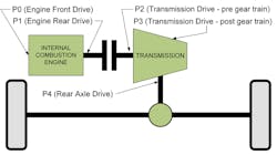
2. The hybrid community has adopted a shorthand code to identify the placement of the electric machine into the chassis subsystem. This system generates labels to indicate each location where the electric machine couples into the powertrain system by using a set of Px indicators.
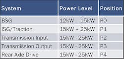
The hybrid community has adopted a shorthand code to identify the placement of the electric machine into the chassis subsystem. This system generates labels to indicate each location at which the electric machine couples into the powertrain system by using a set of Px indicators. The indicators, P0 through P4, have a number that increases as the power insertion point traverses to the rear of the vehicle (Fig. 2).
The power level of the belt-driven starter-generator (BSG) is the smallest due to its insertion point being at the front-end accessory drive (FEAD) of the engine, where the transfer of torque must be coupled through a steel belt. The remaining points of chassis insertion, P2-P4, are all capable of higher power levels, as they’re coupled through steel gears.
Furthermore, the higher-power machines have the added functionality of being able to provide traction assist to the ICE. That means the electrical power source can increase the acceleration of the vehicle in addition to what’s provided by the ICE. In some configurations, it’s conceivable that the electric power source can move the vehicle on its own, with the ICE switched off. This depends on the amount of traction assist available from the electric machine and its placement in the chassis subsystem.
48-V Subsystems
The 48-V to 12-V power converter will be a required addition to the dual-voltage system. The requirement to provide power to the 12-V system, without the existence of a 12-V alternator, demands this component. The need for bidirectional behavior and high efficiency also calls for specialized design methodologies.
Typical power range for these converters is in the 1- to 3-kW range. To maintain high efficiency over this large power range, designers often opt for popular multi-stage buck-boost converter. The buck topology permits power to flow from the higher voltage side down to the lower voltage side. Similarly, the boost topology permits power flow in the opposite direction.
The multi-stage design permits the sharing of many individual converter subcircuits, to be combined into a high-power design. While the converter output is heavily loaded, all subcircuits would be operational. When the converter output is lightly loaded, many of the subcircuits would be switched off, thus providing lower losses and better efficiency.
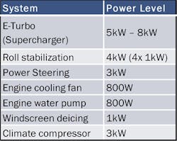
There’s a wide variety of conceivable 48V loads; many of the higher power loads weren’t able to be realized with 12-V systems—the highest of them being an electronically controlled supercharger. Since a supercharger needs to accelerate to extremely high speeds in fractions of a second, it requires large amounts of transient power. A typical supercharger drive consists of a low inertia three-phase motor, driven by a three-phase power inverter. Peak power levels can reach upwards of 8 kW, even though it has a relatively low average power.
These wide power range profiles are a perfect match for 48-V systems. Many other vehicle subsystems are also ideally suited to the 48-V architectures, in both single and three-phase configurations. A listing of potential 48-V loads can be seen in Figure 3.
Other 48-V Systems
The 48-V battery system consists of a lithium-ion battery, which requires much more care and handling than a lead-acid battery. For this reason, the 48-V vehicle requires a battery management system (BMS). This system is responsible for monitoring cell voltage and cell temperature so that the battery can be safely charged. This situation also becomes much more complicated due to the 48-V systems’ ability to produce regeneration. During the opportunities where the vehicle battery’s state of charge is low enough, regeneration can be commanded. However, careful control of the BMS is crucial to prevent overcharging or overheating.
Moreover, 48-V circuits have a more complicated set of requirements for their fusing and contacting. It’s not clear that the 12-V blade-type fuse will provide adequate arc prevention if used in 48-V systems. Also, since the relay contact distance required for a 48-V system will be greater than that for the 12-V system, fuses and relays will need to be redesigned. Because both of these components’ requirements can be easily solved by the use of semiconductor devices, it’s quite likely that these problems will be solved by electronic solutions.
Conclusion
The addition of 48-V systems to a 12-V vehicle will provide opportunities for designers to achieve the fuel-efficiency improvements required in today’s automobiles. It will also greatly increase the need for new and innovative power electronic circuitry. Although many variations of 48-V architectures will be forthcoming, the final verdict will come from automotive customers after weighing the features and benefits versus costs.
John Grabowski is a systems design engineer at ON Semiconductor.
About the Author
John Grabowski 1
Systems Design Engineer
John Grabowski is a Principal Applications and Marketing Engineer in the Power Systems Group of ON Semiconductor, Ann Arbor, Mich. He joined ON (formerly Fairchild) in 2007 after a 30-year career at the Ford Motor Company Research Laboratory. He has been involved in circuit and software design as applied to electric-, hybrid electric-, and powertrain-related automotive applications. More recently, his group is active in advancing the application of high-power semiconductors for automotive electrification.


