Download this article in PDF format.
Reliable sensing in an automobile can make a trip that much more enjoyable. Something as simple as a reliable door closure indicator can remove distractions while driving, or better yet, quickly indicate when the children’s back-seat door has opened. These instances certainly require latches, but equally as crucial as the fastener is having knowledge of closure.
It’s critical to select the proper sensor type—one that’s immune to the automobile’s environment—for the driver’s sanity. The automobile’s harsh environment, such as rich magnetic fields, vibration, dust, dirt, oil, or moisture, can cause the best of sensors to fail.
The act of sensing the closure of a door can seem like a simple proximity-sensing task. Proximity sensors detect an object without touching it, and they, therefore, don’t cause abrasion or damage to the object. The sensor candidates for this proximity-sensing task are the photodiode/LED pair, capacitor, and inductor.
Such a system sends an LED light in the direction of a photodiode. As the photodiode accepts the luminance of the LED light, a photodiode current, with predictable linearity, identifies the closeness of the LED. The capacitor sensor uses electrical fields to quantify the proximity of an object. The inductor, in combination with other inductors and a metallic material, uses exclusively magnetic fields to identify close-proximity events. The sensor accomplishes this by generating a signal in one inductive coil and sensing the reactive signal in the two other coils along, with the introduction of a magnetic plate.
So which sensor will provide the best, most reliable, repeatable, rugged results? As we close in on the best sensor, the best place to start is to define the automotive environment.
Sponsored Resources:
- ZMID5201/02/03 Inductive Position Sensor IC
- Blog: Superior Alternatives to Magnetic Position Sensing
- ZMID5201 Inductive Position Sensing Starter Kit
- How To: Design Low-Cost Contactless Position Sensors
Automotive Environment
When it comes to electrical systems, this automotive environment is the worst of the worst. The automotive shell, frame, and interior are rampant with oil, moisture exposure, extreme shock, vibration, effects of explosive gases, and dust-laden environments. All of these elements create an extremely hostile micro-cosmos. And in this environment, the expectation is that the electrical systems operate failure-free.
Optical Proximity Sensor
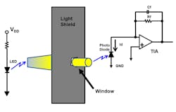
The optical proximity sensor consists of an LED that’s ON, a photodiode, a transimpedance amplifier (TIA). and a light shield with a window. When the position of the LED causes light to shine on the photodiode (through the light shield), the photodiode generates current through the amplifier’s feedback resistor (Rf) (Fig. 1).
1. Optical proximity sensors tend to suffer from LED reliability and unclean environmental issues.
The proximity system in Fig. 1 has LED reliability and unclean environmental problems. In terms of the LED, the device luminance tends to decrease over time. The only solution to this problem is to replace the LED entirely.
Environmental cleanliness is, of course, a key factor—any debris in the space between the LED and photodiode will degrade the reception in this system. If the dirt and debris are chronic, the proximity system will cease to operate correctly. In addition to this environmental clutter, the alignment of the LED and photodiode is easily misaligned due to vibration and extreme shock.
Capacitive Proximity Sensor
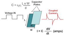
A capacitive proximity sensor can detect and measure a different dielectric or conductive material between the plates. The capacitor sensor is able to measure proximity, position/displacement, humidity, fluid level, and acceleration. A capacitor sensor has two conductive plates separated by non-conductive material or dielectric. The dielectric is typically air, plastic, or ceramic. Figure 2 shows the simple model of a capacitor.
2. A capacitive proximity sensor detects and measures a different dielectric or conductive material between two plates.
The dielectric of a capacitive proximity sensor changes with oil, moisture exposure, and dust-laden environments. However, if the application calls for delta changes rather than absolute change, the capacitor sensor fairs very well. On the negative side, the sensor is sensitive to magnetic changes. With the automobile, these changes can be dramatic.
Inductive Proximity Sensor
An inductive proximity-sensor system detects absolute rotary or linear motion. An inductive position sensor provides an ac signal that determines the presence of metal objects, while providing absolute position information. This technology utilizes induction in a wire loop and eddy currents to detect the position of a metallic target that’s sliding or rotating above a set of printed-circuit-board (PCB) coils.
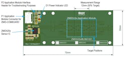
The three coils in this system consist of one transmitter coil and two receiver coils. With an inductive technology, the embedded sensing elements are PCB coils (Fig. 3).
3. This linear inductor PCB layout, reproduced from the ZMID520x Evaluation Kit User Manual, features three copper-trace coils arranged as a transmitter coil and two receiver coils.
The PCB has three copper-trace coils arranged as a transmitter coil and two receiver coils. In addition, the system uses a metallic target to modify the magnitude of the signals in the coils, where the target can be any kind of metal, such as aluminum, steel, or a PCB with a printed copper layer.
The transmitter coil’s signal induces a secondary voltage in the receiver coils, depending on the position of the metallic target above the coils. The two receiving coils sense the target’s position through the transfer of a magnetic signal and creation of eddy currents. The ZMID520X sensor IC (Fig. 3, again) then demodulates and processes the secondary voltages from the receiver coils.
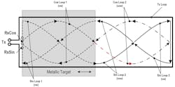
The IC, which connects directly to the three sensing elements or PCB inductor coils, drives the first of three coils and an external capacitor to form an LC oscillator. The receiver coils pick up the oscillator's signal and generate a magnetic field within the transmit coil area (Fig. 4).
4. Shown are the linear PCB trace connections.
The three options available in the ZMID520x family have identical sensing inputs with differing output capability. The ZMID5201 produces an analog output providing a 100% position map with a voltage range from 250 to 4750 mV. The ZMID5202 produces a PWM output that delivers a 100% position map to a duty cycle of 5% to 95%. And the ZMID5203 has a 12-bit Single Edge Nibble Transmission (SENT) output. The SENT protocol conforms to SAE J2716, Revision 2. In addition, SENT Pause and CRC can be programmed according to SAE J2716, Revision 3.
With all devices, there’s a digital One-Wire Interface (OWI) pin for device communication and programming. The bidirectional OWI makes it possible to adjust the device’s operation, such as coil polarity, sine/cosine offset, and linearization for imperfect coils, and provides protection and error diagnostic capability.
The ZMID520x family is fully qualified to automotive standard AEC-Q100, grade 0 up to 150°C ambient temperature.
Getting a Sense of Confidence
The inductive proximity-sensing system is rugged against all odds. When the technology is pitted against its optical and capacitive cousins, it outperforms them both.
This PCB/integrated-chip combination is immune to the automotive-rich magnetic fields, where high currents and the wiring harness generate magnetic fields to an unbearable level for most sensors. Beyond that, it’s immune to vibration, dust, dirt, oil, and moisture. This technology even endures excessively shocking events.
Inductive position sensing technology is paving new roads in the automotive industry, and IDT's ZMID520x family of devices brings value to the table by increasing the reliable, repeatable ruggedness of your automobile.
Sponsored Resources:


