Choosing the Right Automotive Sensor for Throttle Control
Download this article in PDF format.
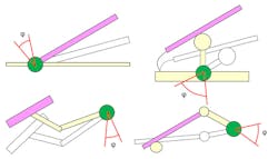
As you accelerate down the road and use your gas pedal to throttle in the appropriate amount of energy, you expect a smooth implementation from your foot to the motor. The electronic throttle control systems of today’s automobiles contain an accelerator pedal position (APP) sensor. The APP sensor monitors the throttle pedal position and sends an electronic signal regarding when to open or close the throttle body (Fig. 1).
1. Some possible pedal designs, with the sensor position indicated in green. The measurement range is usually below 60°.
Although the APP sensor survives the entire lifespan of the vehicle, it will occasionally fail, wear out, or need to be replaced. Primarily the APP sensor, because it’s located on the floorboard next to the vehicle firewall, will experience a degree of exposure to high heat. This sensor solution survives maximum motor temperatures and is an ideal replacement for the APP sensor.
There are several alternative sensors for the APP. In this article, we will examine resistive, magnetic, and inductive sensors.
Sponsored Resources:
- Liquid/Fuel Level Gauge Demo
- How To: Design Low-Cost Contactless Position Sensors
- ZMID520x Inductive Contactless Position Sensors
Pedal Position Mechanics
The first electronic throttle control (ETC) system was introduced in the 1990s. At this time, the replacement of the physical link between gas pedal and throttle became a complete electronic control system. This system had a pedal sensor, throttle sensor, and actuator, as well as the necessary control unit.
The ETC technology allows for a straightforward implementation of advanced features, including cruise control and vehicle-stability control. The proper ETC operation accounts for relevant safety requirements; therefore, the gas-pedal sensor safety requirements are equally demanding.
The vehicle manufacturer trends continue to strive toward comfort. This requirement translates to tight gas-pedal sensor specifications. The specifications include high linearity, low hysteresis, as well as small offset and sensitivity drift over lifetime and temperature. All of these specifications are in the spirit of maintaining the smooth feel of controlling the engine.
Finally, the tight accuracy requirements walk hand in hand with more reliable gas-pedal sensors. This comes from the automotive industry’s safety requirements. Typically, one addresses this with short-circuit and wire breakage detection, redundancy, and digital interfaces with error-detection algorithms, all of which are not available with potentiometers.
In addition, gas-pedal systems utilize integrated techniques to reduce system space and weight. Because the gas-pedal sensors are not easy to access, a drawback of the embedded gas-pedal sensors is the increased repair costs for faulty sensors. Consequently, the failure rate of gas-pedal sensors must be lower, which favors contactless sensing, as is the case with inductive sensors.
Resistive Sensors
The APP uses the configuration of resistive sensors in a potentiometer arrangement. Of the sensor family, potentiometers are the most prolific and very inexpensive. The capability of the potentiometer enables rotational position measurements. The mechanical potentiometer has a mechanical wiper that requires a mechanical manipulation. Total resistance of this device equals the resistance from end-to-end as the wiper divides the total, as it moves linearly from one end to the other.
The main advantages of the potentiometer include:
- Ease of implementation
- Analog output
The main drawbacks of the potentiometer include:
- High wear and, consequently, failure rates
- Nonlinearity over the life of the device
- Inferior signal-to-noise ratio
The safety and reliability potentiometer drawbacks impact its usability in gas APP sensor applications. The gas-pedal sensor’s environmental conditions for the automobile include high temperatures, vibration, shock, exposure to water, and gases. All of these conditions contribute to early potentiometer failures.
This older technology also exhibits other reliability problems. Potentiometers typically allow about 5 to 25 million full cycles, but the limited, specific angle range of the gas pedal further impacts the reliability of the potentiometer. The abrasion is most significant in this limited range, causing nonlinear or failing behavior. One can observe these failure mechanisms as wear in the resistive tracks and material build-up on the wipers. Finally, as a passive device, wire breakages, overvoltages, or internal defects are undetectable.
In summation, potentiometers are a suitable solution for systems where low cost is a key factor. Given the electronic throttle control system is a safety-applicable application, most new sensors use magnetic or inductive contactless principles.
Magnetic Sensors
One way to measure a rotational position is with the contactless magnetic principle. Many manufacturers of gas-pedal sensors use linear Hall sensors with a surrounding ring magnet for gas-pedal angle detection. These devices have advanced digital interfaces, which transmit status and temperature information to the controller or processor. Modern magnetic sensors incorporate reliability and safety features, such as error detection.
The existing automotive Hall sensors have various output protocols available, such as Single Edge Nibble Transmission (SENT) and pulse-width modulation (PWM), with 16-bit resolution. The main disadvantages of magnetic systems are that these sensors are sensitive to electromagnetic interference (EMI), require temperature compensation, and stress affects the sensor’s performance.
Humidity and the subsequent swelling of molding material of the sensor module may lead to drift of mechanical stress on the silicon chip. The treatment of the stress drift is limited, but advanced stress compensation successfully averts stress-dependent signal drifts.
Inductive Sensors
The inductive position sensors, for use in automotive, industrial, medical, and consumer applications, operate on the principles of a wire-loop induction and eddy currents. The sensing element consists of three PCB coils that directly connect to an integrated circuit (IC). One of the three coils transmits an ac signal to the other two receiver coils. The IC, transmit coil, and a capacitor form an oscillator that converts dc to ac (LC oscillator). This LC oscillator generates a magnetic field within the transmit coil area where the receiver coils pick up this signal.
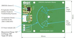
2. This rotary inductive application board with a 130° range uses an IDT ZMID5203 Inductive Position Sensor IC.
The inexpensive construction of the PCB inductive element uses the board’s metallic trace material (Fig. 2).
The voltage generated in the receiver coils depends on the position of the target, whereby the areas shielded by the target generates a weaker secondary voltage compared to unshaded areas by the target. The arrangement of the two receive coils is such that these secondary voltages are phase-shifted by 90°.
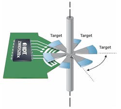
This phase shift generates response curves that resemble a sine and cosine waveform over the range of target travel. By having a sine and cosine shaped response, a ratiometric measurement is possible. The ratiometric measurement improves the robustness of the system because the output signal remains stable, even if the gap varies between coils and target (Fig. 3).
3. Here’s an example of an IDT side-shaft rotation, off-axis, 6 × 60°.
The PCB inductor provides an ideal sensing technology. The construction of the inductive element has a thin sheet of conductive material with output connections perpendicular to the direction of current flow. When subjected to a magnetic field, the PCB inductors respond with an output voltage proportional to the magnetic field strength. The voltage output is minimal (μV) and requires additional electronics to achieve useful voltage levels.
The reasons for using a particular inductive sensor configuration varies in accordance with the application. Cost, performance, and availability are always considerations. The designer should weigh the features and benefits of a given technology along with the specific requirements of the application.
For example, the general characteristics of IDT’s inductive sensors are:
- Non-contact sensor
- No magnets required; reduces system cost
- No wear, highly reliable
- Wide operating temperature range for harsh environments
- Various output protocols available, including analog, SENT, and PWM
- Tolerance to mechanical misalignment
- Single IC for on-axis and off-axis sensor designs
- Full resolution for every angle range
- Stray field immunity and ISO 11452-8 compliance
- Ultra-thin position-sensor design options (~2 mm)
- High accuracy in all applications (angle, linear, and rotary)
- AEC-Q100 Grade 0 automotive qualification
Throttle Control Sensor Comparison
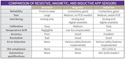
The resistive (potentiometer), magnetic (Hall-effect), and inductive (coil) sensors all play a role in the APP sensor market place (see table).
Solution Options/Paths
The critical element in the APP system is the sensor. Main sensor choices for this task are the potentiometer, Hall effect, or inductor. The potentiometer is available as a mechanical package, which presents its own challenges in terms of reliability. The Hall-effect sensor provides good resolution and error-detection performance; however, it is not compliant to the general automotive standards and qualifications. The inductor solution, on the other hand, meets all of these requirements.
Sponsored Resources:


