Download this article in PDF format.
Sensing technologies for electronic situational awareness has seen lots of progress, driven by all the attention currently being given to autonomous vehicles (AV). The advances in materials, topology, and processes have resulted in a new generation of sensor systems, which in turn enable the creation of new, cost-effective solutions.
This explosion in targeted automated solutions has been enabled by the significant reduction in cost in advanced subsystems. The need for accurate, reliable, and efficient systems to support AV location and movement has thrown the spotlight on a core infrastructure technology, the inertial measurement unit (IMU).
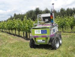
Formerly the realm of the military and other “cost-is-no-object” application spaces like aerospace, IMUs are now available to be used in the most cost-sensitive applications. One example is the European VineRobot project, which is developing a novel unmanned agricultural robot equipped with several non-invasive sensing technologies to monitor vineyards. Until now, it has required direct human action to determine critical vineyard yield aspects like vegetative growth, water status, and grape composition
Multiple issues are involved in developing a robot that can operate in the real world, and they’re exacerbated by application-specific issues. In the case of a vineyard robot, both technical and business challenges need to be addressed.
Vineyards differ in a significant way from most other agricultural situations. The most notable aspect is terrain, as most vineyards in Europe are on hillsides and other, often steep, landscapes. This creates several challenges to an agricultural robot for vineyards, as tire profile, vehicle suspension, and motor torque become very important when driving off the vertical.
Another serious issue arising from operating (alternating up and downslope) on a steep incline is the higher importance on vehicle presence. What angle are the tires to the face? How steeply and in what direction is the vehicle tilted? There are lots of considerations when going from a 2D to a 3D surface for navigation purposes. Things get stickier quickly when you add issues like vehicle orientation for proper sensor operation.
That’s where the IMU comes in. It provides backup position information for vineyard navigation. In addition, an IMU handles all other aspects of managing a robotic vehicle in an environment where vehicle position and angle are not only critical for safe maneuvering, but also for proper sensor suite functionality for the intended application of vine growth and health monitoring.
On top of that, this custom solution must work in the smallest and steepest of European vineyards—and it has to be cheap. Winemakers operate on some of the thinnest margins, and like many small farmers, are very vulnerable to catastrophic issues that can render a season unprofitable. That’s why this new accessibility and cost-effectiveness in the latest generation of IMUs is critical. It enables solutions to be developed for spaces that previously couldn’t afford such a sophisticated solution (Fig. 1).
1. The AGV developed by the European VineRobot project uses non-invasive sensing technologies to monitor vineyards for vegetative growth, water status, and grape composition.
Such a useful solution previously could not be created, because navigational systems like the IMU were too expensive. With a good IMU now available for well under $100, the scope of application spaces that can develop their own targeted robotic vehicle solution has expanded to apply to anyone with a reasonable amount of resources.
An IMU determines an AV’s speed, angle, and direction, often adding magnetic-field information for added directional input. This task is done by using an integrated suite of accelerometers, gyroscopes, and sometimes magnetometers. An important task for the IMU is to provide baseline vehicle information to supplement GPS signals, to create a completely accurate snapshot of all the AV’s motion and position characteristics.
But how do you know you have the right tool for your application? Many products are out there, and frankly you can probably pick almost any of them and have something that will work in your system for your application. However, an integral part of engineering is optimizing performance—using a solution that isn’t the most efficient means, of course, you will never achieve the best performance.
To paraphrase Charles Dickens, the difference between the right solution and the almost-right solution is the difference between lightning and a lightning bug.
Application Driven
First things first. What kind of AV is going to use the IMU? Will it operate in a closed facility, or does it have to operate outdoors? What kind of accuracy do you need?
Beyond knowing orientation in three dimensions (three degrees of freedom), you should also know the additional dimensions of rotation, for six degrees of freedom. Then, once you add magnetometers, a device is considered by the industry to have nine degrees of freedom.
These requirements can all be easily addressed by reading the spec sheet and checking off the level of functionality you want. Most vendors and manufacturers offer several levels of product to enable scaling.
Here’s where you decide on primary device characteristics—this is the critical stage. A good example would be magnetic sensing, a feature not available in all IMUs. If you buy an IMU with one and your project turns out to not need magnetic information, it’s wasted time and money. It’s almost as bad (but definitely not nearly as big a nuisance) as initially buying an IMU without magnetic sensing, and then later determining (usually due to changing customer requirements) that you really do need that sensing capability.
That’s not to say that just because you can relatively easily satisfy this part of this selection process, it doesn’t mean it shouldn’t have the same level of diligence as for any other aspect of the design process. Here’s where you also can weed out first-echelon needs like sensitivity and accuracy, culling the obviously inapplicable and creating a short list for further research.
Body Issues
Beyond the application, among the first concerns is the device footprint. Needless to say, if the device is too large for the space provided (and sometimes ironically, if it’s too small), you will have significant issues integrating it into your product.
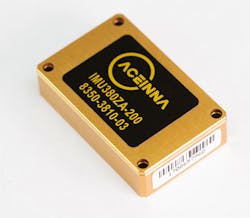
If you don’t need a lot of robustness or protection from the elements, you can get IMUs with nine degrees of freedom in packages smaller than two square inches, and with protective packaging and coatings smaller than 16 square inches. By properly establishing all environmental and operational parameters, you can optimize size vs. performance and get the best solution (Fig. 2).
2. Modern IMU units can be very compact—as small as 24 × 37 × 9.5mm—for easy integration into a wide range of design projects.
Not only do you need to consider the device itself, but also the clearances for any cables for power and signal required. Something as relatively trivial to performance as whether the connectors are on the top, bottom, or side can make or break the selection decision.
Other than footprint, packaging issues involve materials (cost and weight), any coatings for ruggedness or water resistance (cost, weight and size), and mounting requirements. Accessibility may or may not be an issue, based on desired operational lifetime and maintenance requirements.
Power Play
The other primary consideration involves the issue of power. Whether the IMU is going into a large wheeled or winged AV with big batteries, or a small quadcopter with barely enough power to keep itself in the air, does make a critical difference.
The good news here is that the latest IMUs integrate very efficient (and small) microelectromechanical systems (MEMS)-based sensors. That means they will be both powerful and accurate, while consuming less power than legacy gyroscopes and electromechanical systems.
When selecting an IMU, you’re going to want one that draws very little power, while accepting as wide a voltage as possible to ease system integration. Depending on your battery configuration and other subsystem needs, some IMUs may not be able to cost-effectively interface with your power bus.
The Internals
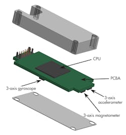
Of course, an IMU is only as good as the sensors inside of it. How good is the gyro performance? The magnetic sensors? The latest IMUs have advanced MEMS-based inertial sensors, and 3-axis magnetic capability, while some devices may either use legacy sensing technology or low-grade MEMS (Fig. 3).
3. Designed for complex autonomous applications, the latest IMUs have advanced MEMS-based inertial sensors (3-axis accelerometer and 3-axis gyroscope), as well as 3-axis magnetic capability.
Software is an often-overlooked aspect of the IMU selection process. If the communication protocols aren’t up-to-date, or the system interfaces aren’t effectively implemented, you will never achieve your solution’s potential. The right software infrastructure should provide a simple and clean graphic interface to display, record, playback, and analyze all of an IMU’s system parameters.
Having good software also expands the capabilities of the system. For example, an advanced solution with user-configurable settings to optimize system performance can address highly dynamic applications more effectively than a system with a limited number of parameters.
Under a Cloud
This could be considered a part of the first step, but once you have your communication protocols set up and your signal bus established, the question shifts to what level of integration and functionality you desire in the system. That can be dealt with after you determine your form factor and figure out how it will be powered.
Part of specifying the desired IMU is also to determine what peripheral functionality it will provide. At the minimum, the IMU will be a subsystem that tells the AV its location, where it’s pointed, and how fast it’s moving that way (and which direction on the compass, if you have magnetic functionality).
The IMU can also provide the vehicle systems with sensor data for basic operation. Many AVs are designed for use in upgraded consumer or commercial vehicles, which often have their own sensors systems for stability and roll detection, so the IMU serves the navigation system. If you’re creating a vehicle from scratch, however, you can use the IMU to replace many of the sensors previously required for that job, simplifying your system and reducing your bill of materials (BOM).
Speaking of the BOM, the recent significant drop in the cost of an IMU and other advanced subsystems has also created a shopper’s opportunity for design engineers. There’s lots of competition in the space right now, so it’s as almost as important to evaluate costs as it is to evaluate performance.
This is especially critical when looking to replace legacy devices—it’s easy to be pleasantly surprised at the cost of the new stuff to the point you don’t perform due diligence in pricing. This also leaves you open to being second-guessed by procurement when they swap your selection out for a less costly unit themselves.
Looking Forward
Whenever you design a complex system, success or failure is often determined by how well you can integrate the various subsystems involved. Specifying the right device for the task, especially for critical navigation subsystems, will help ensure development of an optimal design. This is especially critical when addressing an application space as unforgiving of inadequacy as autonomous vehicles.
Mike Horton is the CTO of ACEINNA.


