Thermal Modeling: How to Meet EV High-Power Charging Requirements
Download this article in PDF format.
The next generation of vehicles will generate, process, and communicate much more data than current vehicles. Wireless networking via mobile technologies (e.g., 5G, V2X) enables communication with other vehicles or with the surrounding infrastructure, as well as makes software updates over-the-air (OTA) possible.
At the same time, high current power will be transmitted within electrified cars. Today’s electric cars already have in excess 120 kW of engine power. The high-power levels required for this performance produce strong electromagnetic fields that require protection of nearby signal lines and electronic components against interference and malfunction (high data rates of up to 20 Gbits vs. high power).
Put simply, the physical layer will play a key role as the backbone of future vehicle functionality and ensuring its reliability. That means low-voltage data connectivity networks and high-voltage (HV) drive systems must work ultra-reliably and safely in parallel.
The Electromobility Framework
Powertrain electrification serves to reduce vehicles’ consumption of fossil fuels despite a worldwide increase in the demand for mobility. It’s the only way to meet the ever-more stringent limits on greenhouse-gas (CO2) emissions both in the medium- and long-term.
Long distance in electric vehicles (EVs) will be enabled by fast charging with dc and a future charging power of 350 kW, which is classified as high-power dc charging (HPC DC).
The Importance of HPC
Until recently, greater attention was dedicated to the driving side of electromobility instead of the issue of charging. This can be attributed to a lack of maturity in the business models of the two industry segments that are involved—carmakers (OEMs) and energy producers.
The typical EV use case varies globally. While European EV drivers expect their car to be capable
of occasional long-distance trips, Asian EV drivers tend to use their cars for short distances in mega cities. HPC DC would enable EVs to be used in all cases. However, simply expanding the inner-city ac charging station network would not be sufficient because lower power charging times would result in prohibitively long waiting times and queues.
Increasing battery capacities to lengthen driving ranges can only be exploited in a helpful way if “bigger” batteries don’t lead to even longer charging times. With a charging power of 350 kW, it would be possible to gain up to 300 km of additional range within up to minutes maximum. This would turn EV “refueling stops” into acceptably short breaks (comparable with combustion-engine-driven cars), and the dc charging station would quickly be available for the next vehicle. However, 350 kW of charging power at currents of up to 500 A are the peak load for the complete current path from the charging station to the vehicle battery.
The high current, flowing along this path, causes high heat losses since the electric resistance of all components (connectors, cable) inevitably generates heat. This heat loss needs to be factored into the design and dimensioning of all electrically conductive components to avoid overloading or overheating, or a controlled derating of the charging current should the battery begin to overheat during charging. While derating protects the battery, it also prolongs the charging time. This divergence of objectives needs to be solved in an optimal way.
Thermal management can do this by predicting the exact state of all components in every segment of the structure at any time.
The Challenge of HPC
HPC DC represents a peak load state for the electrical system in an EV. The high-charging current of HPC DC causes a significant rise in temperature in all components. This is further exacerbated when the vehicle isn’t moving, because there’s no convection available for cooling. Therefore, to facilitate HPC DC, the complete electrical system from the charging point to the vehicle battery needs to be designed and dimensioned electrically and thermally.
A major contributor to this challenge is that the higher the current, the larger the required cable cross-section to carry the power at the same level of voltage without overheating. Within the vehicle, this is primarily a matter of weight and available space. For example, it makes a considerable difference, in terms of cost, weight, and bulk, as to whether a 50-mm2 cross-section or a 95-mm2 cross-section conductor between the inlet and the battery will suffice.
An attractive option is to increase the voltage, so the same amount of power can be transmitted at a lower current level. While dimensioning electrical components potentially accounts for unwanted additional mass in the vehicle, it also approaches weight limits in the case of fixed charging cables (mode 4 cables). If HPC DC is to be a realistic proposition, the over-dimensioning of the cable and all other electrical components must be avoided.
Today’s Electrical Component Design
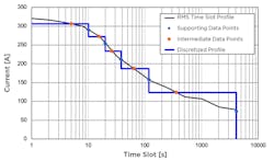
To date, design of electrical components along the high-current path has been based on assumptions that aren’t really suited for either the dynamic load profiles of driving or the requirements of HPC DC. Existing standards are based on static load points originally used for the design of relays and (switch) fuses, which are determined by statistical methods reflecting the frequency at which they occur and their importance. This leads to the root-mean-square (RMS) values representing static conditions (Fig. 1).
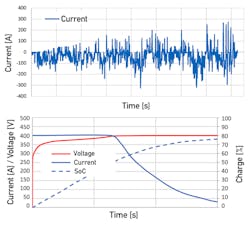
1. This is the quantification method behind the current profile in Fig. 2.
Electrical interconnection components are designed in accordance with this type of load profile—which does not reflect reality—and a safety margin of 20% is added. The actual load profile in an EV, though, differs dramatically from previous vehicle applications and their RMS values (Fig. 2).
2. Driving profile compared to an HPC load profile.
Figure 2 explains why thermal design is so essential for charging. While driving results in a very dynamic current profile, consisting of load changes between high peaks and lows, the constant high load during HPC DC isn’t reflected at all in the load profile derived from driving. To facilitate a peak load of 350 kW charging power requires a different approach to designing the electrical components.
While the electric energy stored in a battery is typically retrieved over a time span of several hours during driving, three to four times this amount of energy flows into the battery during HPC DC within minutes. Accordingly, the complete high-voltage/high-current path has to be analyzed at a system level to understand its behavior during charging (Fig. 3). Root mean squares aren’t very helpful for this as was detailed earlier.
3. Shown are differently stressed components along the current path of an EV.
It’s essential to know where a constant load can cause overheating that might lead to a critical system state. This thermal angle must be analyzed more closely. The methods currently employed don’t deliver the needed answers.
As a result, current systems are statically over-dimensioned due to safety considerations. With 350 kW of charging power, this approach isn’t sustainable due to the implications on weight, installation space, and usability.
To address this challenge, TE Connectivity is developing a new design approach within its ZVEI activities (German Electrical and Electronic Manufacturers’ Association). The thrust of the approach is to dynamically determine the temperature increase caused by components, as well as the heat dissipation in the system, via established principles of simulation (as used for electrical systems). This methodology makes it possible to examine component design earlier to predict its performance during operation.
Model-based thermal simulation provides a verifiable basis for future load profiles that facilitate a proof of safety, reliability, and availability of all interconnection components along the high-voltage/high-current path.
The Importance of Thermal Simulation
The physics of transmitting electric energy causes power dissipation in the shape of heat losses along the wired energy flow. The root cause is the electrical resistance (measured in ohms) of all metallic conductors.
This resistance is known for every element of the high-voltage path. However, the ohmic resistance changes with the temperature increase during operation. The amount of power dissipation that occurs at a specific component can be calculated for a certain current, voltage, and temperature—albeit only for a stationary state when all paths of heat dissipation are balanced.
Existing methods to dynamically calculate the complete high-voltage path on a system level aren’t very practical. To apply a well-known method such as finite element analysis (FEA), it would be necessary to make multiple calculations in rapid sequence for each operating point. It’s clear a continuing thermal calculation in real time (in the vehicle) requires a different methodology that needs much less computing power.
One part of the challenge is that heat dissipation along a high-voltage path leads to a comparatively slow system. Depending on an individual component’s mass and the adjacent available heat sinks, the individual component will react differently to changing load profiles.
Lightweight components with a limited chance for heat dissipation can become a bottleneck for thermal management. If the generated heat can’t be sufficiently dissipated, the component will temporarily become an adiabatic element (i.e., a condition with no heat exchange with the environment) without any chance to externally influence its heating-up process. Thermal bottlenecks of that type need to be understood so that no unnecessary limits or stress are based on the system.
Furthermore, heat dissipation occurs on several paths. In addition to conductive heat dissipation within the material, there’s also the share of heat radiation and heat dissipation via cooling air or coolant flows (convection). For each component along the high-voltage path, the mix of these three elements will be different.
When electrical components heat up, they also undergo an aging process that changes the electrical (and or mechanical) properties of the component over time. The stronger the heat entry, the faster this aging process and the smaller the residual performance level of the component.
The Challenge of HPC
It’s therefore necessary to find a different tool that can provide a timely definition of a safe and economically feasible current-path design for HPC DC—and provide proof of its safety. Using a proven systemic thermal simulation makes it easy to automatically test an almost unlimited number of possible load profiles in advance. This will reveal potential thermal bottlenecks in the system that can be addressed via design changes.
Employing this methodology can lessen subsequent troubleshooting effort. The reduced investigative effort can be considerable because the thermal system is so complex. The exact root cause may not be in the originally diagnosed component, but rather in an adjacent component along the heat path.
Systemic Simulation Method
This advanced systemic simulation methodology, which calculates heat losses along the high-voltage path under dynamically changing load conditions, is based on Kirchhoff’s circuit laws. His “point rule” and “loop rule” state that the sum of all currents at a “point,” and the sum of all voltages in a “loop,” must be zero.
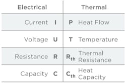
At the same time, the rule states that energy is always conserved. That means the current that’s transformed into heat (heat loss) due to the electrical resistance isn’t lost. Instead, this heat energy is exactly equal to the difference between the electrical energy flowing into the circuit and the energy that’s available at the target system. Equivalent circuit diagrams exploit the immediate and linear relationship between electrical and thermal behavior (Fig. 4).
4. The correlation between electrical and thermal values forms the basis for equivalent circuit diagrams.
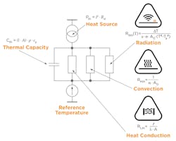
Consequently, equivalent circuit diagrams (Fig. 5) serve to simulate the linked electrical and thermal behavior. In the same way that a voltage sends a current through a resistor, a temperature difference causes heat transport. The different physical forms of transport (conduction, convection, radiation) are each represented by a resistor. Stored algebraic equations in the component model continually calculate the heat generation depending on the applied current and voltage, as well as the ambient temperature.
5. As seen in this equivalent circuit diagram for thermal simulation, resistors represent the three ways of heat dissipation.
Based on this heat generation, the different possibilities for heat dissipation are represented by resistors (thermal barriers) and thermal masses/capacities in the equivalent circuit diagram. The diagram represents the heat transport resolved over space via conduction within the material, via radiation, and via convection.
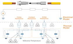
Using this fairly simple method, it’s possible to simulate individual components (e.g., a contact), whole products (e.g., a connector, such as in Fig. 6) or a high-voltage path, as heat generation and heat dissipation are predictable through loop-formation.
6. A connector is broken down into loops: There’s equivalence between the electrical points of contact in a connector and the thermal simulation.
Once cable models are made available from the cable manufacturers, the intermediate sections also can be calculated. In addition, it’s possible to integrate components from different manufacturers (as per the on-board net)—all it requires is to enter the manufacturer-specific electrical parameters. Within the model, these parameters are applied to algebraic equations that follow Kirchhoff’s circuit laws. In essence, the model describes the heat generation and heat exchange with the environment.
The simulation can determine, for example, the location of heat sources and heat sinks; when a temperature level becomes critical and begins to shorten a component’s service life; how a component integrates into a larger cluster; and where adiabatic states can be found and what impact they’re making.
During the original model development, iterations between simulation and testing (raw data from lab testing) served to refine the algebraic part of the model until the accuracy of the prediction matched the test results.
With the resulting simulation methodology, dynamic load profiles can be tested for each component on the high-voltage path with a minimum of computing power.
Safety Gain
The computing power needed for thermal simulation based on equivalent circuit diagrams is so low that it’s feasible to run this procedure as a continuous routine task on a typical automotive electronic control unit (ECU). Actual load profiles of real-world driving can thus be calculated in real time.
The simulation delivers data that helps improve functional safety. Simulation and sensor data mutually complement one another as heterogenous diagnostic routines. For automated vehicles, which require multiple redundancy for safety reasons, this can contribute to the safety concept.
Designing HV Components for the Vehicle
Systemic thermal simulation strongly advances the load-oriented design of high-voltage components for the vehicle toward real operating conditions. As manufacturers know, it’s highly valuable to be able to predict the performance of a component during its development phase. The systemic and dynamic thermal simulation precisely reveals the expected effects resulting from wear and aging during operation. Thus, a complex system like the high-voltage path can be simulated and its behavior can be predicted. In addition, simulation can cover a breadth of testing that would never be achievable in the testing lab.
For more information, visit https://www.te.com/high-power-charging.
Marco Wolf is Principal Field Applications Engineer at TE Connectivity.

