An LED driver IC for automotive applications must meet many requirements. It must be flexible, implementing multiple functions like high beam, low beam, fog lights, daytime running lights (DRLs), position, and turn-signal lights (Fig. 1). It must have a high dimming ratio in applications like head-up displays (HUDs) to produce a clear image in bright sunlight and a subdued image that will not obscure a driver’s vision at night. In addition, it must be robust enough to withstand the transient high-voltage dump produced by an automobile battery.
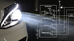
1. Shown is a car with a modern low beam having Modern Low Beam with daytime running lights.
The current intensity must be very accurate, since it controls the LED color. The PWM dimming frequency must be above 100 Hz to be undetected as a flicker by the human eye. A high and well-controlled PWM switching frequency above the AM frequency band is required to reduce radio frequency interference (RFI). Spread-spectrum modulation is also necessary to meet electromagnetic-interference (EMI) standards. Finally, high efficiency helps reduce heat generation and improves automotive system reliability.
In this article, we review the necessary features for automotive LED drivers to safely interface with the car battery while providing high performance in a flexible architecture for ease of reuse in many applications. Subsequently, we will introduce a novel IC that meets these requirements.
Powering the LED Driver
Powered from a car battery, the LED driver input voltage is typically 12 V, but it can be as high as 16 V on a fully charged battery. Vehicles that employ start/stop technology experience large voltage dips when the engine starts, so the lower limit for the power source can be 6 V or lower.
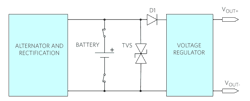
If the car battery is accidentally disconnected from the alternator during a charge, a voltage surge as high as 120 V is generated. This voltage surge is clamped by a transient voltage suppressor (TVS) whose clamping range must be above the maximum battery voltage (16 V) and below the breakdown voltage of the front-end voltage regulator (for example, 36 V).
A reverse-polarity protection diode is also required to protect the system against accidental battery polarity reversal when the battery is disconnected and reconnected during maintenance.
Figure 2 shows the typical front-end protection and regulation electronics as they interface with the battery.
2. Typical car protection and regulation front end.
Dimming
Dimming is a ubiquitous function in many automotive lighting applications and an important safety feature for LED headlights. The human eye can barely detect light dimming from 100% to 50%. Dimming must go down to at least 1% or less to be clearly discernable.
In particular, head-up displays (Fig. 3) need a high dimming ratio to produce a clear image in bright sunlight and a subdued image that will not obscure the driver’s vision at night. With this in mind, it’s not surprising that dimming is specified by a ratio of 5000:1 or higher. Given that the human eye, under proper conditions, can sense a single photon, there’s practically no limit to this function.
3. A HUD display requires a high dimming ratio to be effective.
Since current must be kept constant to preserve color, the best dimming strategy for LEDs is pulse-width modulation (PWM), where the light intensity is modulated by time-slicing the current rather than by changing the amplitude. The PWM frequency must be kept above 100 Hz to prevent the LED from flickering.
With PWM dimming, the limit to the minimum LED “on/off” time is the time it takes to ramp up/down the current in the switching regulator inductor. This may add up to tens of microseconds of response time, which is too slow for LED headlight cluster applications that require fast and complex dimming patterns. Dimming in this case can only be performed by individually switching on/off each LED in a string by means of dedicated MOSFET switches. The challenge for the current control loop is to be fast enough to quickly recover from the output-voltage transient due to switching in and out of the diodes.
Basic Headlight System
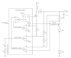
A basic headlight system architecture that can accommodate a series of LEDs uses a boost converter. In the boost controller IC of Figure 4, one of the three feedback loops (CURRENT LOOP) ensures tight control of the output current. The other two feedback loops perform overvoltage protection (OVP LOOP) and overcurrent protection (OCP LOOP) for the string of 12 diodes, which creates 42 V across the string (3.5 V per LED).
4. Three feedback loops are included in this common boost LED-control-system configuration.
In addition to current and voltage control, the IC must be equipped with all of the features previously mentioned (dimming, spread spectrum, etc.). High-side current sensing (via the resistors RS) is required to protect the LED system in case of shorts from the output to the ground or battery input.
Flexible LED Controller Architecture
Ideally, an LED controller should have a flexible architecture that supports multiple configurations that can implement different features. We have discussed the boost configuration, but we should also consider the buck-boost configuration. A buck-boost mode configuration is necessary if the diode string is short, for example, two or three LEDs (7 V or 10. 5V) against a battery voltage that can vary from less than 6 V (cold crank) up to 16 V.
If the concern is input-to-output isolation, then a SEPIC (discontinuous output current) or a Ćuk (continuous output current) converter may be the right solution. A single controller that supports many architectures has clear advantages of economies of scale and ease of reuse.
High-Dimming-Ratio Controller
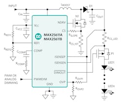
As an example, the single-channel high-brightness (HB) LED driver shown in Figure 5 is used for automotive front-light applications such as high beam, low beam, DRLs, turn indicator, fog light, and other LED lights. It can take an input voltage from 5 to 36 V and drive a string of LEDs with a maximum output voltage of 65 V.
5. The single-channel HB LED driver is used for a variety of automotive front-light applications.
This 36-V LED driver IC offers highly flexible schemes for driving LEDs, allowing either boost, high-side buck, SEPIC mode, or buck-boost mode configurations. The PWM input provides LED dimming ratios of up to 5000:1, and the REFI input offers additional analog dimming capability. The IC’s built-in spread-spectrum modulation improves electromagnetic-compatibility performance. In addition, the device can be used in zeta and Ćuk converter configurations.
For high-efficiency applications, the switching frequency is internally set at 350 kHz with the A version. For applications favoring small passives and small PCB size, the B version’s frequency is set at 2.2 MHz. The IC is housed in a 4- × 4-mm 12-pin SWTQFN-EP package with exposed pad to maximize head dissipation.
The TVS in Figure 2 can be implemented with a Littelfuse TPSMF4L20A TVS diode, having a clamping range between 22.2 and 32.4 V. The diode D1, also in Figure 2, can be implemented with a diode controller (MAX16141) and two external MOSFETs for minimum power losses.
Nazzareno (Reno) Rossetti is an analog and power-management expert and Yin Wu is a semiconductor business professional at Maxim Integrated.
Further reading:
MAX25611 Automotive High-Voltage HB LED Controller
Achieve Superior Automotive Exterior Lighting with a High-Power Buck LED Controller
Flexible LED Controller Simplifies Automotive Exterior Lighting Design
