Transitioning from Class-AB to Class-D in Automotive Audio Systems
Download this article in PDF format.
The most common audio power amplifier operates in the Class-AB mode. It provides the greatest amount of output power with the least amount of distortion. The downside is that it consumes quite a bit of power. In addition, to get rid of heat, heat sinks and ventilation are generally needed.
However, these amplifiers are gradually being replaced by Class-D amplifiers, especially in automotive applications. Class-D amplifiers are switches that are more efficient and produce less heat than their Class-AB equivalents. If you’re designing automotive audio equipment, it’s time to take a look at Class-D amplifiers as an alternative to Class AB. Upgrading from Class-AB audio amplifiers to Class D brings about some significant benefits in automotive audio.
Sponsored Resources:
- Minimize amplifier size and thermal load in automotive audio applications
- Don’t be worried about the transition from Class-AB to Class-D audio amplifiers
- Start evaluating with our 2.1Mhz Class-D audio amplifier today
Class D Basics
Class-D amplifiers have been around for over a decade, but their adoption has been incremental as engineers have learned the pros and cons. At the same time, development has continued making Class-D amplifiers better than ever. Here’s a brief summary of the benefits and disadvantages of the Class-D amplifier versus the traditional Class-AB amplifier.
Class AB
Benefit: Lowest distortion—total harmonic distortion plus noise (THD + N) is less than 0.1% for high fidelity.
Disadvantages: Inefficient—maximum possible efficiency is about 60%. High power consumption and significant heat generation. It’s also larger in size.
Class D
Benefits: High efficiency—greater than 90%. Less power consumption and lower heat generation. Smaller size. Very high-power potential (400 to 500 W) in a small package.
Disadvantages: Higher distortion level with THD + N up to 10%, but it’s still intelligible. Noise generation.
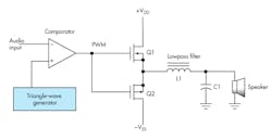
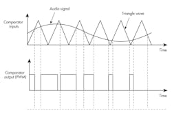
The operation of a Class-D amplifier explains its benefits and disadvantages. Figure 1 shows a representative circuit. Figure 2 illustrates the circuit operation.
1. Shown are the main circuits of a basic Class-D amplifier.
2. The combination of the triangle wave and the audio input signal to the comparator produce the PWM signal.
A high-frequency triangular-wave signal is generated inside the Class-D IC. The frequency is in the 50-kHz to 2.1-MHz range. It’s applied to one input of a comparator. The other comparator input is the audio signal to be amplified.
The comparator generates a pulse-width-modulated (PWM) signal that contains the signal to be amplified. PWM varies the duty cycle of the pulses while maintaining a constant frequency. The PWM signal drives two switching MOSFETs that produce a high-voltage PWM signal. A lowpass filter then smooths and averages the PWM to recover the amplified original audio signal.
The output MOSFETs consume no power when they’re off, and when they’re on, their very low “on” resistances consume little power. The switched output is responsible for higher power and efficiency. However, the switched output contains harmonics that must be filtered out. The switching output naturally produces some noise or interference.
For example, if the switching frequency is 400 kHz, the second and third harmonics (800 kHz and 1200 kHz) fall right inside the AM radio band (535 kHz to 1705 kHz), potentially causing an electromagnetic-compatibility (EMC) issue. The output filter plays a major role in dealing with those problems. A better solution, though, is to use a higher switching frequency.
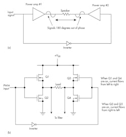
The typical Class-D amplifier is usually connected in bridge-tied-load (BTL) configuration like that in Figure 3a. The circuit looks something like Figure 3b. This arrangement has several benefits. First, you may have noticed in Figure 1 and both positive and negative dc supplies are needed. This is a nuisance in that it’s an extra expense and complication, especially for an automobile that has a single 12-V supply. There are dc-dc converters available, but the BTL arrangement eliminates the problem.
3. The bridge tied load provides a power boost and eliminates the need for a negative supply. Illustrated are the concept (a) and the switches that produce a balanced output (b).
Another benefit is that the speaker load gets twice the normal voltage on the positive and negative peaks of the input. Since power is proportional to the square of the voltage (P = V2/R), much higher power is available. Virtually all Class-D IC amplifiers use this bridge configuration with a balanced speaker output.
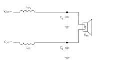
With a balanced load, the filter is usually divided as shown in Figure 4.
4. This is a common lowpass-filter configuration for a balanced load. The higher the switching speed, the smaller the inductors that are needed for proper filtering of the PWM signal.
The Rationale for Class D
Each passing year, more electronic equipment is being added behind the dashboard. Some examples include the radios, the sound system for streaming music, hands-free Bluetooth phones, and voice-response units, to name a few, with more undoubtedly to come. It comes as no surprise, then, that the space behind the dashboard is at an all-time premium. Class-D audio amplifiers offer a solution thanks to their small size. Their high efficiency over a traditional Class-AB audio amplifier keeps the heat to a minimal level in that small space.
Thus, the small space requirement addresses one the main reasons many auto audio engineers are considering making the switch from Class AB to Class D. Class-D amps clearly take up less space.
Another reason is the fear of electromagnetic interference (EMI). Automobiles must pass tough EMC tests and any potential source should be evaluated. With proper design, the 2.1-MHz switching frequency, and a good filter, EMI will be well within the test standards.
The Current State of the Class D Art
A good example of a current Class-D amplifier that targets automotive use cases is Texas Instruments’ TPA6304-Q1, a tiny 2.1-MHz, 4-channel analog input Class-D audio solution for automotive infotainment applications. The TPA6304-Q1’s 2.1-MHz switching frequency allows customers to significantly reduce inductor size as well as PCB size, eliminate AM radio interference, and optimize total system cost.
The device provides four channels at 27 W into 4 Ω at 10% THD+N and 45 W into 2 Ω at 10% THD+N using a 14.4-V power supply. It operates over a wide range of supply voltages from 4.5 to 18 V. The TPA6304-Q1 is ideal for dashboard head units and external amplifier systems, as it occupies little space and generates minimum heat. The chip also incorporates I2C diagnostics and protection.
An evaluation module for the TPA6304-Q1 is available. It features USB and analog input options plus an on-board USB-I2C controller for GUI-driven evaluation.
Sponsored Resources:
