There are many wise old sayings within the aerospace industry. One of those sage aerospace tenets conveys the differences between scientists and engineers: When the rocket gets off its pad and the payload successfully reaches its destination, the scientists have had another breakthrough. But let that rocket blow up on the pad and the engineers have screwed up again.
An EMC-induced launch failure generally is not as spectacular as a solid-fuel rocket blowing up on the pad, but EMC has certainly accounted for a large number of very expensive mission losses. Some of these launch vehicle (LV) and spacecraft (SC) combinations can run around $2,000,000,000. Consequently, an EMC engineer working in the aerospace industry doesn t want to be branded as one of those engineers that screwed up again.
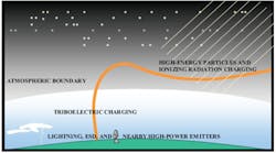
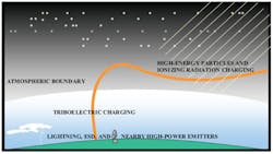
EMC Environmental Changes During Launch
To help prevent that from happening, just remember P R O B L E M S: short for Power, Radiated emission and susceptibility, Out-of-band interference, Bonding and grounding, Lightning, ESD, Multipaction, and Space charging. This is a memory hook for spacecraft EMC design and environmental requirements that must be addressed to ensure mission success.
These items cover the essential EMC environmental requirements from MIL-STD-464A and MIL-STD-1541A for launch vehicles, spacecraft, and any associated electronic flight hardware. This article will not cover all the requirements of MIL-STD-1541A, plus there always are some mission-specific requirements that must be considered.
But first, here are a few general comments about the electromagnetic environment (EME). EMC is all relative. For a given set of environmental conditions, at a given location, and at a specific instant in time, the device has EMC. To optimally assure EMC, a long-term EME survey should be made starting at the manufacturing location, continuing through the transportation phase to the storage location, and then finally adding the usage environment.
A composite worst-case then could be developed from this information and the device designed accordingly. At each of these locations along the way, the EME is continually changing.These changes can proceed slowly as new equipment is developed that uses the RF spectrum, or the environment can change rapidly from a clear day to one filled with thunderstorms and lightning transients.
Because of the difficulty of maintaining an up-to-date composite database covering a large geographic area, military and commercial standards are used at a cost of either overdesign or underdesign. Even then, it is prudent to use an up-to-date specification. At this time, the space industry is using MIL-STD-461C and MIL-STD-1541A, both approximately 20 years old.
Now, back to P R O B L E M S.
P = Power
P is for electrical power quality. LV/SC electronic equipment obtains its power from storage batteries. In addition to providing power, batteries also act like a large value capacitor of approximately 17,000 F/A-hour and do a good job of reducing low-frequency interference on the power line.
In general, the launch vehicles are operational for such a short time that charging is not required. Spacecraft, on the other hand, may be placed in parking orbits and have such long life expectancies that the batteries are float-charged using solar arrays. If there is not enough sunlight along the SC trajectory to its destination, then radioisotope thermoelectric generators (RTG) are used as the power/charging source.
Power distribution for space operation is very much like shipboard power since most of the time the power system is ungrounded. This permits a single fault to chassis without shutting down the entire system.
But to use an ungrounded system, all subsystems must be isolated from the chassis, and the system/subsystem must be able to tolerate the increased common-mode noise that results from this approach. Alternatively, subsystems may be tied to chassis using a capacitor. This can provide RF grounding while maintaining DC isolation.
When a DC grounded system is needed for ESD protection, the ground generally is isolated from the battery return by 1 kΩ to 10 kΩ. This provides an ESD or space charge ground return while limiting any fault current.
Although not recommended, especially for EMC, spacecraft occasionally are designed using the structure as the DC return. Since there is a common shared power system, this results in increasing common-mode coupling between subsystems.
There is some savings in weight, but it can be argued that the wire weight savings are offset by the increase in power filter weight and the reduction in system reliability. Under no circumstances should a magnesium structure be used for current return. Arcing across structural joints may ignite the magnesium, and all that money will disappear in the midst of a brilliant white flame.
MIL-STD-1539 and MIL-STD-1541A provide the power quality requirements. Here is a brief summary:● Voltage Ripple: Maximum of 500 mV peak to peak.● Short Duration Spikes: Peak value for spikes less than 50 's is limited to three times the nominal load voltage with an impulse strength less than 0.14 • 10-3 V-s.● Surges: Positive and negative surges must return to steady-state limits in less than 5 ms and 100 ms, respectively.● Load Switching and Load Faults: Exclusive of spikes, surge amplitude shall remain between 65% and 130% of the nominal load voltage. Multiple loads have some relaxation.● Power Subsystem Faults: Exclusive of spikes, the surge amplitude during faults shall remain between 0% and 175% of the nominal load voltage.Other than wiring runs to pressure and temperature sensors, power cables generally are the next longest runs. To minimize crosstalk and radiation, most LV/SC cables are shielded.
Overall cable shields and individual pair shields determine the maximum attenuation that can be achieved by the cable. The minimum attenuation typically is the result of large apertures created by discontinuities at the connectors.
Internal pigtails are used to continue the individual pair shields but degrade the crosstalk between pairs by opening the shield. Both the pair pigtails and the overall cable shield are continued through the connector by clamping the shields to an internal ring. The connector plug then is mated to the connector jack, and the bonding impedance at the backshell and the box determine the leakage of the connector.
MIL-HDBK-83575 specifies the cable EMC control requirements. The principal techniques are the following:● Segregate wires by power/current, sensitivity, and frequency.● Use twisting and shielding to minimize internal and external coupling. ● Bond all conductive parts. R = Radiated Emission/Susceptibility
Today's launch vehicles and spacecraft use MIL-STD-461C and occasionally MIL-STD-464A to control radiated emission and susceptibility. In many cases, the qualification is based on the hardware's similarity to previous hardware, inspection, analysis, or sometimes test. This puts the requirements about 20 years behind the current MIL-STD-461E DoD EMC specification, and MIL-STD-461F is due out this year.
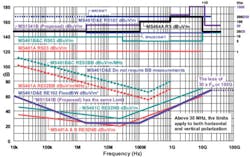
A comparison of the radiated requirements of MIL-STD-461 and the system requirements from MIL-STD-464A and the newly proposed MIL-STD-1541B are shown in Figure 1. One of the most significant changes has been the radiated susceptibility requirement levels.
Figure 1. MIL-STD-461A, B, and C; 461D and E; 464A; and 1541B (Proposed) Limit Comparison Please click here to see larger image.
Since the creation of MIL-STD-461, the radiated susceptibility levels have increased by 46 dB with a growth of 32 dB occurring since the MIL-STD-461C revision was released. Every revision to the MIL-STD-461 specification has increased the radiated susceptibility levels while reducing the radiated emission levels, reflecting the real-world situation of an increasingly noisier RF environment.
It is not true that a collection of hardware where each item meets the MIL-STD-461 specification will result in a system that meets the same requirements. In addition, systems used in space applications have some peculiar requirements that ground-based systems don't have.
The system needs to work and perform its intended function. After all, it is very difficult to implement a fix when the malfunctioning device is in low earth orbit or beyond. For that reason, stringent EMC requirements are levied against the system.
MIL-E-6051 was used for early LV/SC and required subsystems to meet MIL-STD-461. Then in 1973, MIL-STD-1541 was released. This standard was developed specifically for LV/SC systems and written as a companion document for MIL-STD-461A. Although a new document, it did retain some of the characteristics of MIL-E-6051. The system had to be functional in an environment that was essentially defined by adding 6 dB (20 dB for ordnance) to the worst-case emission profile.
The MIL-STD-1541A (1987) revision was released as a companion to MIL-STD-461C (1986) and added power-system transient controls, design requirements for composite structure, and controls on interference that might result from spectral and orbital congestion. There were minor changes carried over from MIL-STD-1541 to 1541A relative to the MIL-STD-461C radiated emission requirement and no changes to the radiated susceptibility requirement.
That is where we are today'stuck back in time 20 years with some items that have been previously approved by similarity still meeting 40-year-old requirements. An attempt was made to move forward in the development of ISO 14302, but there was strong resistance to having equipment EMI requirement references beyond the MIL-STD-461C version.
It is in everyone's best interest to test like you fly. The players are not necessarily doing this because of the cost. It is expensive to prove that each major element of the LV/SC/launch site is compatible with the environments that may be encountered during manufacture, transportation, and launch. What does not appear to being considered is the three-year setback associated with a failure and that the loss of one $800,000,000 LV/SC system buys a lot of EMC upgrades and engineering services even at today's prices.
Even when MIL-STD-1541A is not a requirements document, it is a great guide for controlling EMI/EMC on LV/SC.
Keeping in mind that MIL-STD-1541A was written as a companion document to MIL-STD-461C, the minimum requirements are shown with procedures listed from MIL-STD-461E:● CE01/CE101 conducted emissions, power leads, 30 Hz to 10 kHz.● CE06/RE03 antenna measurements 10 kHz to 40 GHz. For equipment operating at frequencies greater than 30 MHz, the frequency range specified in MIL-STD-461 shall be extended to the 30th harmonic or 100 GHz, whichever is less. Relaxation of these requirements is subject to special restrictions.● CS01/CS101 conducted susceptibility, power leads, 30 Hz to 150 kHz.● CS02 conducted susceptibility, power leads. Modulation of the susceptibility signals is required and must have the modulation characteristics that will have the worst-case effect on the test sample as shown by analysis.● CS06 transient susceptibility.● CS07 inrush current measurement.● RE01/RE101 radiated emissions, magnetic field, 30 Hz to 100 kHz. This requirement will not likely be needed unless the SC has magnetic sensitive equipment onboard.● RE02/RE102 radiated emission, electric field 10 kHz to 18 GHz.● RS03/RS103 radiated susceptibility 10 kHz to 40 GHz. Modulation of the susceptibility signals is required and must have the modulation characteristics that will have the worst-case effect on the test sample as shown by analysis.● ESD not a MIL-STD-461 test but required by MIL-STD-1541A.● RADHAZ out of date but the limit is 10 mW/cm2.Subsystems and equipment shall satisfy the requirements of this standard when operating with a ground network consisting only of the power return conductors, the conductive parts of the component enclosures, and any bundle shields for interconnecting cables. Satisfactory performance shall not depend upon having low-impedance bonds between component enclosures and a highly conductive ground plane.
O = Out of Band
Certain classes of equipment are extremely sensitive to RF energy and cannot meet the radiated susceptibility requirements that are imposed on other classes of equipment. These RF sensitive devices suffer from unique interference problems occurring at their operational frequencies and require special EMC hardening measures to permit them to be used in the system.
Likewise, a transmitter cannot meet the low-level emission requirements at its operating frequency. As a result, receivers and transmitters are exempt from meeting MIL-STD-461 at their operating frequencies. Consequently, these devices are subject to out-of-band interference.
The primary out-of-band problems are desensitization, signal distortion, demodulation, and intermodulation. Prevention of these problems is about the only thing that can be done. Once the interference is in the passband of the receiver or transmitter, there are no easy fixes.
In a LV/SC configuration, the flight termination system (FTS) receivers are the most important RF devices, and their interference-free operation is a primary concern in the design of a LV/SC. Culprit out-of-band RF signals must not cause the FTS to destroy the LV by mistake. In addition, these signals must not prevent the FTS from destroying the LV when it has been properly commanded to do so.
Out-of band interference falls into two primary categories:● From range-controlled sources that are within the same frequency band but are using a different technology, such as AM, FM, pulse, or SSB.● From nonrange-controlled sources that are in the same or adjacent frequency bands.In the first case, since the sources typically will be co-located and under control of the range safety officer, most interference can be managed by using frequency guard bands, directional antennas, timesharing, and amplitude control. This includes sending the RF police over to the RF source and asking the operator to turn off the offending radio.
In the second case, such as nearby marine and military radios and Radar, amateur radio stations, and TV, interference is out of the control of the range officer, and if an interference problem does occur, it is much more difficult to locate and eliminate.
Plus, the LV may fly closer to an emitter during launch and be exposed to higher field levels than it is exposed to on the launch pad. There also are downrange emitters that can cause strong fields at the vehicle. In this case, the trajectory of the vehicle must be considered and the ascent field levels and signal-to-noise ratio of the FTS and other RF systems predicted for each mission based on its flight trajectory.
In addition, once the spacecraft separates from the vehicle, the on-orbit fields must be considered if it will be in a near-earth orbit. It is common for tracking radar to use spacecraft as targets of opportunity, and field levels from emitters can be in the hundreds of volts/meter.
Moreover, there are other emitters that produce levels in the thousands of volts/meter that SC trajectories may inadvertently cross. Table 1 shows the worst-case ascent and on-orbit field levels being called out in the proposed MIL-STD-1541B which, if approved, would become the companion document to MIL-STD-461E/F.
Table 1. Worst-Case RFI Susceptibility Levels for Various Conditions
A study performed by the U.S. Army's Tactical Operations Center (TOC), Ft. Monmouth, NJ, disclosed that poor electrical bonding, grounding, and shielding were the major factors in generating and propagating broadband noise into co-located communications equipment.
The study indicated that, once the receiver picks up the RF noise, it affects the S/N+I, and there is very little that can be done to improve the situation. As a result, prevention is the primary and often the only solution to co-site interference problems.
There are several other factors of interest summarized as:● Performance degrades and intermodulation products increase with increased communications traffic.● Reducing the concentration of RF sources can be used to control intermodulation. ● Although increased separation reduces coupling between culprits and victims, performance degrades with increased communications range because the intentional signal is attenuated, degrading the S/N+I ratio. ● Performance improves with increased frequency separation between Tx-Rx pairs.● Adding external transmit and receive filtering can be used to control intermodulation.● Directional antenna orientation can be used to control intermodulation and will provide 10-dB to 20-dB reduction.B = BondingBonding is used to interconnect conductive elements within conductive structures, surfaces, and circuits to establish a low RF impedance across the joint. Bonding is an essential requirement to provide the following:● A low resistance power return path.● Shock and fault protection.● Minimum EMI.● A quality antenna ground plane.● Lightning protection.● Minimum ESD.● Minimum problems from space charging.
A low-resistance bond will minimize the voltage that might otherwise be developed across the joint. MIL-STD-1541A states that the bonding between the conductive parts of the vehicle structure, component enclosures, and cable shields shall conform to the requirements for Class R of MIL-B-5087. Conductive films on dielectric materials, such as thermal blankets, shall be bonded to the ground network with a resistance ≤10 Ω. Bonding resistance between the conductive and semiconductive items of the vehicle system shall be <1 Ω.
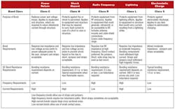
MIL-B-5087 has been canceled, but the essential requirements have been moved to MIL-STD-464A. The various bonding classes are summarized in Table 2.
Class R bonds are specified ≤2.5 mΩ. There is nothing magic about this number other than it means that a very good bond is required. Good clean metal-to-metal surfaces should have no difficulty meeting this requirement.
However, direct contact between dissimilar metals that would result in electogalvanic corrosion must be avoided. This precaution is particularly applicable to external connectors in the immediate vicinity of antennas. The probability of the existence of nonlinear or rectifying junctions between dissimilar metals is high, and the existence of nonlinear junctions in the presence of high-intensity, high-frequency fields may create spurious out-of-band signals.
The effect of possible lightning strikes will be considered in the designing of bonding. It is not unusual for a LV to be on the launch pad for months in the rain, salt fog, lightning, and dust.
Proper bonding to the ground system of all metal that is not a direct part of the circuit will prevent these materials from possibly becoming antennas and resonant circuits. Bonding also will prevent arcs or changes in impedance between portions of the structure that could generate large RF noise signals. Proper bonding and grounding also are necessary to avoid conductive coupling, low-impedance ground loops, and galvanic corrosion of the fabricated equipment.
The bonding practices of MIL-STD-464A will be used as guidance in addition to these industry bonding practices:● Permanent type bonds are more reliable and therefore preferred.● Direct-type bonds such as formed by individual welded, sweated, or brazed joints are lower impedance and are preferred.● Bonds should afford good metal-to-metal contact over both mating surfaces of the bond joint. The mating surface should be clean and free from any conductive finishes. Bare, clean, metal-to-metal contact will ensure a low impedance connection between mating surfaces.● Bonding halos or interlacing straps will be used to terminate the cable shields.● Bonds should be measured. There is no way to determine bond quality by inspection. Part 2
Part 2 of this article focuses on the L E M S Lightning, ESD, Multipaction, and Space charging of spacecraft EMC PROBLEMS that must be addressed to ensure mission success. It will appear in EE's May issue.
About the Author
Ron Brewer currently is a senior EMC/RF engineering analyst with Analex at the NASA Kennedy Space Center. The NARTE-certified EMC/ESD engineer has worked full-time in the EMC field for more than 30 years. Mr. Brewer was named Distinguished Lecturer by the IEEE EMC Society and has taught more than 385 EMC technical short-courses in 29 countries and published numerous papers on EMC/ESD and shielding design. He completed undergraduate and graduate work in engineering science and physics at the University of Michigan. e-mail: [email protected]


