Download this article in .PDF format.
Identifying a new technical requirement on a program of record is both a major headache for the program office and a positive circumstance for engineers looking for a problem to solve. As simple as it sounds, B-1 Integrated Battle Station (IBS) was seeking a test methodology for locating deficiencies in the digital video interface (DVI) cable runs between the multifunction displays and the video processor. The application of a time domain reflectometer to the problem was only going to expose shorts and opens. More fidelity was needed to characterize the DVI cable assembly in the cockpit—seeking twists of twisted pair and minimum bend radius installation issues. The treatment of the cable assembly (connectors, conductors, terminations) as a transmission line enables a wideband, multiport S-parameter view of the problem, which opens up a much more sensitive measurement. The challenge is to produce test results in a repeatable, easy-to-understand GUI display that will stand up to realistic environmental conditions.
At the core of any tester, there are three common, essential functions: Power supply, display, and a single board processor. All three require technical tradeoffs:
- Power supply must be robust to handle worst-case temperature and have switchable output elements for power savings while the tester is on batteries. Additionally, a FET bridge for output shorts-protection is a desirable feature. Power supplies are literally the heart of the system and typically don’t receive much attention.
- Display should be LVDS sunlight-readable, color, capacitive touchscreen and rugged. HD displays are wonderful for graphics, but the cost tradeoff isn’t attractive for a test tool. A 24-bit LVDS display simplifies the interface to the single board computer without incurring excessive cost.
- Single board computer must be reliable with adequate cache memory and expandable to host a wide variety of USB-tethered modules. PMC is a reasonable form factor (small and power efficient) but a full-function single board computer with LVDS for the monitor and mSATA hard drive drives the design toward PC/104.
PXI has been the standard for industrial and most military test sets since VME went out of vogue (except with the Navy) in the ‘90s. The backplane is rugged and there exists a wide variety of functional modules that can be integrated. However, reduced size, weight and prime power considerations drive test tool designs into modular form factors. There will always be a requirement for PXIe chassis, especially when creating new test methods and analysis tools, but the small form factor testers will increasingly be integrating functional blocks via USB and PC/104 interfaces.
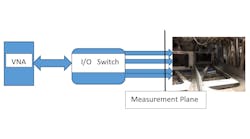
Because the I/O Switch is located at the virtual measurement plane (with the exception of any lead cables), it becomes the critical module that selects the conductor pair under test as well as the launch pad for a wide range of tests from insertion loss to continuity. The expansion possibilities are intriguing, considering an FPGA generating an eye pattern signal for the overall integrity of the high-speed cable assembly. Utilizing a standard 3.3 Vdc bias applied to individual pins adds the wire-map capability.
Furthermore, the VNA 2 Port S-Parameter measurement is a very sensitive method for obtaining insertion loss on cable assemblies that include couplers (MIL STD 1553) and stubs that are hard to disconnect physically. Finally, the capability of testing RF cable assemblies for mismatch and damaged cable/connectors is now within reach using this concept. “Normal troubleshooting” scenarios are extremely rare—often problems with Mil/Aero systems cross the digital/analog/RF boundaries and a single tester that is versatile and capable of isolating faults is well within the realm of possibilities for next gen MROs.
High-speed digital cables are pervasive across platforms where 10GHz Ethernet and DVI cable assemblies are being installed on aircraft to support special SIGINT, COMINT, and IMINT configurations. It will be increasingly important to identify test tools that can accurately locate and assess cable assembly anomalies and failures.
Bob Appenzeller is CEO of Dayton, OH-based DragoonITCN, having started a small SETA shop in support of DoD programs in 1992. He is a practicing engineer supporting troubleshooting and modifying aircraft for various missions worldwide. Appenzeller can be contacted at [email protected]


