Power Management, Chapter 6: Power Supply System Considerations
This articles is part of the Power Management Series in the Power Management section of our Series Library.
Download this article as a .PDF eBook.
Overall design of the power-management subsystem involves several system-oriented issues. Adequate space must be available for the selected power supply. Make sure the power supply will fit in the space provided for it. Therefore, make sure the package type you want, such as open-frame, enclosed, brick, encapsulated, etc., will fit in the allocated space. In addition, make sure there is enough room adjacent to the power supply to allow it to cool if you are using natural convection cooling. If you are using forced air cooling, make sure that you have sufficient air movement around the supply.
One aspect of space availability is the standards for size of rack-mounted power systems, such as 1U, 2U, 3U, etc. The term 1U defines one rack unit of height that equals 1.75 in. of rack height. A 2U rack mount height would be 2 x 1.75 in., or 3.5 in. high, and so on. The 1U, 2U, and 3U heights are maximum dimensions. Individual rack-mounted power supplies must be a bit shorter than the equipment’s overall height to allow for the top and bottom covers. So a 1U-high enclosure-mountable power supply needs to be shorter than 1.75 in.; a 2U enclosure-mountable supply needs to be shorter than 3.5 in., and so forth.
Power Distribution
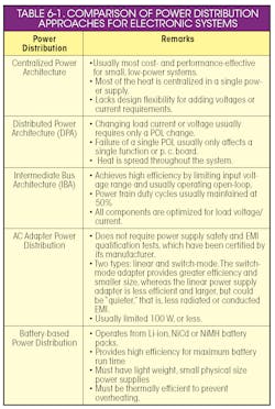
Distributing power in the end-item system depends on the type of power supply used. Five different distribution methods are possible:
Centralized Power Architecture (Fig. 6-1) accepts an ac power line input and produces one or up to five output voltages. As implied, centralized supplies operate from a central location and supply all the power for an electronic system. They are powered from the ac power line and produce a dc voltage output. They may provide one or multiple output voltages. These outputs then provide power to the specific circuits that require the various voltages. For most small, relatively low-power systems, centralized power distribution is usually the most cost- and performance-effective.
6-1. Centralized Power Supply Can Produce Multiple Voltage Outputs
A typical centralized system is the type employed in desktop computers; that is, a single supply provides all the required voltages: +5V, ±12V. (Note: 3V is replacing 5V on many computers as the main logic voltage.) However, the centralized approach can suffer from lack of flexibility.
If the system requires an additional low voltage, the power management subsystem must be redesigned by replacing the entire centralized supply or adding a voltage regulator derived from an existing output. If any existing supply voltage requires a higher current capability, the centralized supply must be replaced.
An advantage for the centralized power supply is the cost associated with powering a small to moderate size system. A single supply with multiple outputs can be more cost-effective than a distributed supply with multiple dc-dc converters.
To minimize power distribution losses, the centralized supplies should be located near the load. For safety and EMI reasons, it should be located as close as possible to the ac entry point, which is often a problematic tradeoff. Although centralized power works well for many applications, it is usually unsuitable for distributing high power at low voltages.
A drawback of the centralized supply is its transient response, which is the ability to react quickly to rapidly changing loads. Centralized power systems may have difficulty responding to transient loads and handling resistive voltage drops. Another potential problem is its characteristic of concentrating heat in one specific area.
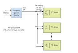
Distributed Power Architecture (DPA) (Fig. 6-2) converts the incoming ac power to a secondary dc bus voltage, using a front-end supply. This dc bus voltage can be 12V, 24V, or 48V and is usually less than 60V. This bus voltage is distributed throughout the system, connecting to dc-dc converter modules associated with specific subsystems or circuit cards.
6-2. Distributed Power Architecture Employs Front-End Power Supply for Multiple POL Mounted on System P.C. Boards
The most popular DPA voltage is 48V used by telecommunication systems. The secondary voltage is bused throughout the system, connecting to dc-dc converter modules associated with specific subsystems or circuit cards. You can locate the front-end supply either in a card cage or in a convenient place within the system. For non-telephone applications, the trend is to use lower intermediate bus voltages, ranging from 7V to 12V. This is because as the speed and complexity of the digital circuits and microprocessors increase, their internal spacings decrease, resulting in reduced input voltages for these devices. Therefore, the secondary buses power local dc-dc converters that output lower voltages. Higher-speed devices use lower voltages.
One common characteristic for front-end supplies is power-factor correction (PFC) that lowers the peak currents drawn from the ac line. This reduces the harmonic content fed back into the power line, which might otherwise interfere with other equipment connected to the same power line.
Among the features of most front-end supplies is the ability to work over a broad ac input voltage range, for example, 85 to 265Vac. Some front-end supplies may be paralleled to increase the available power. Some paralleled supplies may be combined in a 19-in. rack. Models usually include protection features for overvoltage, overcurrent, short-circuit, and overtemperature.
Optional on-board intelligence on some front-end supplies is the ability to communicate with the host computer. Transmitted data can include operational status, such as temperature, current limit, and installation location identification.
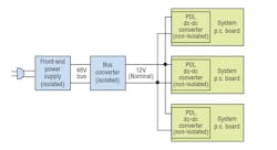
Intermediate Bus Architecture (IBA) inserts another level of power distribution between a front-end power supply and POL. An IBA (Fig. 6-3) employs an isolated bus converter that delivers an unregulated 9.6V to 14V to power to the non-isolated POL converters. As shown in Fig. 6-3, a typical bus converter delivers an unregulated, stepped-down voltage of 9.6 to 14V with a nominal 2000Vdc input output isolation. This converter is ideal for a loosely regulated 12Vdc Intermediate Bus Architecture to power a variety of downstream non isolated, point of load regulators. These modules are suited for computer servers, enterprise networking equipment, and other applications that use a 48V (+10%) input bus.
6-3. Intermediate Bus Architecture Adds an Isolated Bus Converter
Cost savings can be achieved in many applications by replacing multiple 48V in isolated dc-dc converters with low-cost, non isolated POL modules or embedded converters that are fed from the 12V bus converter rail. Implementing one central point of isolation eliminates the need for individual isolation at each point of load, allowing reduced costs, greater flexibility, and savings on board space.
Bus converters achieve high efficiency by limiting the input range and essentially optimizing for a single input voltage. Bus converters are designed for efficiency. Removing the entire feedback path (reference, error amp, optocoupler, etc.) liberates board area and power. Additional parallel MOSFETs may be added to lower on resistances. MOSFET duty cycles in the power train are set and maintained at 50%, and all components are optimized for the voltages they will actually experience and not the voltages they may experience. Also, for high efficiency most bus converters employ synchronous rectifier outputs.
Bus converter packages come in many sizes, from SIPs and SMTs to quarter-brick, eigth-brick and sixteenth brick modules.
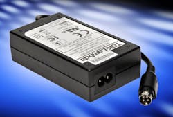
AC Adapter’s distribute power external to the end-item system. They plug into an ac power outlet to provide dc power via a cable and connector that plugs into the end item system. One of the widely used ac input power supplies (Fig. 6-4). They are a cost effective and relatively fast way to obtain a power source for computer peripherals and other electronic devices without going through power supply safety and EMI qualification tests.
6-4. TDK-Lambda’s medically certified DTM65-C8 external power supplies offer a class II input and do not require an earth ground connection and meets the stringent Level VI DoE standards for efficiency. It is housed in a rugged, vent-free IP21 rated enclosure, measuring 106 x 60 x 31mm. AC is applied using a standard IEC60320-C8 cable and DC provided through a four pin Power-DIN connector.
All the OEM has to do is provide the appropriate connector within the associated equipment. Typically, many printers and scanners operate from these adapters that supply a regulated dc voltage. Laptop computers and other portable equipment use these adapters to power the unit as well as charge their battery.
It is important to obtain an adapter that has high efficiency, which minimizes heat dissipation, resulting in an adapter that is small and reliable. Without this high efficiency, the resulting internal temperature rise would be potentially hazardous and a major reliability limiter. In many applications, the adapter may be placed in a confined space, or it may be buried under a pile of cable, so minimizing heat is essential.
Battery-Based Power Distribution requires virtually all circuits designed “from the ground up.” The power management subsystem design involves voltage regulation circuits operating from a battery whose output voltage naturally decreases with use.
Read more articles from the Power Management Series in the Power Management section of our Series Library.


