Download this article in .PDF format
The concept of wireless battery charging, which has been around for several years, is finally gaining some traction in smartphones. Unfortunately, though, the idea has yet to be universally adopted beyond the cell phone due to multiple competing standards and some physical limitations.
Today, with the winnowing of the standards and the availability of integrated circuits that facilitate implementation, wireless charging is set to move ahead. This industry niche is now seeking out new applications, such as the smart watch and other wearables. In fact, almost any battery-powered portable device is a candidate for wireless charging: kitchen appliances, shavers and toothbrushes, shop tools, industrial equipment, medical devices, automotive, and so on.
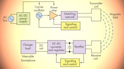
Wireless charging is based on the basic electrical principle of electromagnetic induction. The idea is illustrated in the figure. An ac power source is connected to a coil that generates a magnetic field; the field then induces an ac voltage in another coil in the device to be charged. The coils aren’t electrically connected, but are physically close to one another so that sufficient magnetic field is present to induce a voltage and provide enough power to charge a battery. The Wireless-Charging Concept
Essential components and circuits of a wireless battery-charging system, showing signal flow.
The two coils form a transformer without a common core. The power source or transmitter coil is the primary winding and the receiving coil is the secondary winding. The coils are typically flat spirals of wire with no core.
The transmitter unit takes the ac power-line input that operates a dc power supply, which in turn powers an oscillator signal source at the desired frequency. This signal is called the carrier. Typical frequency range is 100 kHz to 10 MHz.
A power amplifier (PA) boosts the signal level to supply adequate power to the receiver. A matching circuit ensures maximum power transfer from the PA to the primary coil. The transmitter coil is usually embedded in a flat mat or pad upon which sits the device to be charged.
To transfer maximum power, the receiver coil must be perfectly aligned with the transmitter coil. This provides a coefficient of coupling near one. If the coils are misaligned, the coefficient of coupling will be significantly less, thereby decreasing the overall efficiency of power transfer. This physical limitation is one of the main disadvantages of wireless charging.
The ac from the receiver coil is then rectified into dc and applied to a dc-dc converter/regulator that generates the dc output voltage, which goes to the battery charger in the powered device.
A unique feature running through today’s wireless-charging standards is a communications facility between the transmitter and receiver. This communications path allows the transmitter and receiver to detect and identify one another and make internal settings appropriate to the device to be charged. One type of communication path uses coded signals that load-modulate the ac carrier. Another type of communication path employs wireless technology like Bluetooth.
A variation of the inductive-charging method exploits the concept of resonance. A capacitor is connected to the transformer coils to resonate them to the carrier frequency. This produces a higher current in the coils to boost energy transfer. However, its main benefit is that resonant coils needn’t be perfectly aligned for usable coupling. Multiple devices can also be charged this way. Most wireless-charging systems in use today are non-resonant types.
Wireless-Charging Standards
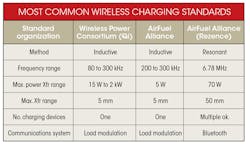
There have been—and still are—multiple standards competing for the wireless-charging business. The two most common standards are those from the Wireless Power Consortium (WPC) and the AirFuel Alliance. Of the two, the WPC’s Qi standard is the more widely used.
Both organizations offer a non-resonant inductive standard; a resonant standard has been available from the Alliance, too, while the WPC also recently added a resonant version. No resonant charging systems are yet commercially available, though. The table below summarizes the basic features of these standards.
Notes: (1) The 6.78-MHz frequency is one of those approved by the FCC for high-power non-communication applications of RF, such as RF plasma or induction heating. (2) Load modulation, sometimes called back-scatter modulation, is essentially low-level ASK of the carrier similar to that used in some RFID tags.
Advantages and Disadvantages
The primary advantage of wireless charging is, of course, the elimination of a charging cable. This benefit also eliminates the generally unreliable connectors and wires associated with the cable. Other advantages are the ease and convenience of charging, and in smaller devices like a smart watch, the elimination of a connector saves space and lowers cost.
Several disadvantages crop up with wireless charging, too. First, there’s the need for a charging pad with the transmitter and its coil, which is an extra cost item. Wireless is also more expensive because of the added coil and other components in the device to be charged. On top of that, the coil adds thickness to a smartphone or other device. Finally, wireless charging is much slower than direct cable charging due to the inherent inefficiency of the method. And don’t forget that the device to be charged must be precisely aligned on the charging pad to ensure optimum coupling.
Designing a Wirelessly Charged Device
Detailed design procedures are beyond the scope of this article, but here are the key steps to a successful design:
1. Select the standard to use. This will usually depend on the market for the product you’re designing. The more common choices are the WPC Qi or the non-resonant AirFuel standard. Acquire the detailed standard specifications from the sponsor.
2. Consider a dual-mode design. Today, it’s possible to make the charged device work with either of the two most common inductive standards, which builds in more versatility.
3. Identify semiconductor vendors with specific chips designed to the standard. If designing for a wearable, seek out ICs that target this category.
4. Look for ICs that can implement a dual-mode design.
5. Select a vendor with evaluation boards and/or reference designs to make the design faster and easier.
6. Carefully select the inductive coils. The coils are the most critical component in the design, both electrically and physically. Special small coils will be needed for wearables or other miniature products (a custom coil may be needed). Work with coil vendors such as Wurth Elektronik to find the best part for your design.
Testing the Design
Testing a wireless design generally requires the following test instruments:
• Digital multimeter (DMM): Used for voltage and current measurements. For ac measurements, be sure that the frequency response of the DMM is sufficiently high to accommodate the signals being measured.
• Digital oscilloscope: Performs routine voltage and current waveform monitoring and measurements. Be sure you have all of the necessary matching probes.
• LCR meter: Used to measure the inductance, Q, and Z of the transformer coils and related capacitance, resistance, and matching network measurements.
• Vector network analyzer (VNA): Useful for S-parameter measurements on the transformer coils and the power amplifier.
Investigate which test-instrument vendors have equipment and software for wireless charger testing.
Several common tests are important for receiver testing:
• Startup sequence
• DC output ripple
• Load transients
• Modulation depth on feedback control path
• Overvoltage protection
• DC-DC and AC-DC efficiency
For details on these and other tests, check out this reference.
Looking for parts? Go to SourceESB.


