Download this article in PDF format.
The world has turned to renewable energy in an attempt to wean itself from depleting carbon-based sources. The increase in the number of solar, wind, wave, and tidal power sources has pushed the need for a highly accurate method of measuring current. The solution is required for several reasons: to ensure accurate billing, have a more granular level of control, and, perhaps most importantly, to ensure the efficiency of the distributed power system.
There are a few ways to measure current. However, the one most suited for renewable applications looks to be conventional ammeters, using shunt resistors to handle the high currents.
The Needs of Renewable Power
Renewable power is not a recent phenomenon. Hydroelectric plants have been popular in some areas for many decades. But for countries trying to switch away from a carbon-based economy, large-scale use of solar and wind power has been the main focus of the new generation of renewable power sources.
Power from these renewable sources differs from conventional sources, such as coal, gas, and nuclear plants. This is because renewables either generate dc power directly, or the power they generate requires some conversion between ac and dc and back. Carbon-based generation inherently produces ac power, which can easily be fed into the grid using substation transformers.
Renewable energy travels a more complex route to the power grid. Photovoltaic panels generate pure dc energy, which must use an inverter to be converted to ac to feed into the grid. Some wind turbines also generate dc, especially the smaller installations seen near homes, farms, and industrial units.
In larger wind-farm installations, it’s possible for the turbines to produce ac power. However, connecting the power to the grid requires the voltage and frequency to be compatible with the grid. In many cases, though, this isn’t the case. The voltage and frequency of the output power is correlated with the rotational speed of the wind turbine, which depends on the wind speed.
One solution is to use a gearbox to sync the turbine speed with mains frequency. The drawback is that this adds complexity to the system, along with extra cost and weight to the overall design. In most cases, it’s preferable to convert the turbine output to dc and then use an inverter to convert it back to ac at the correct frequency and voltage for the grid.
Since almost every renewable power source uses both ac and dc at some point in the power-distribution system, there’s a need to accurately measure both types of power. For ac measurements, current transformers are popular, given that they provide the additional benefit of having galvanic isolation from the measured circuit. But transformers can’t be used for dc power.
There are some measurement tools based on Hall-effect current transducers that can measure both ac and dc current, and they too provide galvanic isolation. The main problem with this type of measurement is the accuracy—it’s normally impossible to get the required accuracy of 0.1% (or better) using Hall-effect current transducers.
A third option is to use ammeters with precision shunt resistors. This type of measurement doesn’t provide galvanic isolation, so this must be included elsewhere.
How Ammeter Shunt Resistors Work
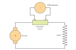
Ammeter shunt resistor operation is well-understood (Fig. 1). Used extensively for current measurement in the past, the basic principles behind the technique are taught in almost every electrical engineering course. The resistors are used to “shunt” most of the current around the measurement instrument. This technique allows measurement of greater currents than is possible using normal ammeters. The low-value resistor is situated in series with the load, creating a small voltage drop across the resistor, which can be measured using a voltmeter. The current is then calculated using Ohm’s law.
1. The schematic illustrates a conventional ammeter shunt circuit configuration.
This is the basic principle behind the operation of the meter. Of course, modern ammeter shunts are a bit more complex. The value of the shunt resistor works with the voltmeter to provide the maximum deflection at the maximum-rated current of the shunt. At that current, the design normally has a voltage drop of 50, 75 or 100 mV. In a typical example, a resistor that would measure a current of up to 100 A, with a 100-mV voltage drop, would have a value of 1 mΩ. For higher currents, a lower value of resistor would be required, with lower voltage drops.
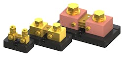
With such a low resistance, it has to be defined precisely in advance, and any other elements in the systems that could cause errors must be eliminated. One way to reduce potential erroneous measurements is to use a four-terminal resistor to keep the load connections separate from the measurement terminals.
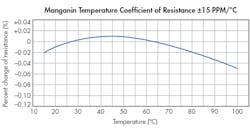
Many materials used to manufacture resistors are susceptible to temperature variation. When trying to measure with an accuracy of 0.1%, the resistor material must have a low temperature coefficient of resistance (TCR). For example, Manganin alloy can be used for shunt ammeter resistors because its TCR is stable over a temperature range of −40 to +60ºC.
2. The substantial four-terminal construction of typical high-current shunt resistors ensures accurate measurement and effective power dissipation.
Shunt ammeter resistors often are required to dissipate a lot of power, since they’re designed to carry the full current of the circuit. The design of the shunt ammeter must take the dissipation into account, using conduction and convection techniques to dissipate the heat. If the device is used in a continuous current, it may need to be de-rated in order to comply with IEEE standards for dc instrument shunts (Fig. 2).
What’s the Best Choice?
One must consider a number of factors when selecting a shunt resistor for a given application, regardless of whether it’s bought off-the-shelf or customized. As mentioned previously, resistance has to be stable over the whole temperature range that will be experienced by the system. The maximum operating temperature for the resistor is generally 80˚C, with normal operation between 40 and 60˚C.
Maximum operating temperature is kept below 80˚C because temperatures above that point cause the resistance to drift and disturb the accuracy of the measurement. If the temperature of the resistance element rises above 140˚C, it will trigger an annealing process, permanently changing the resistance. To minimize the chances of this happening, the correct positioning and orientation of the shunt is vital. If the element is mounted vertically, it will give access to the maximum amount of free air for convection. Even this may not be enough, and the circuit may need forced-air or water cooling (Fig. 3).
3. Manganin alloy provides a low temperature coefficient of resistance.
If the voltage is high during the current measurement, the voltage will naturally be present in both the leads and the instrument, so one must take care. If practical, the shunt should be placed in the ground leg. If the voltage is above 750 V, it’s essential to place it in that spot.
In general, shunts operate at around 66% of their rated maximum current. The exception is if the shunts are intended to measure intermittent or surge currents. In these cases, a higher current can be tolerated without worrying that the resistor element will exceed the maximum-rated temperature. Consequently, the duty cycle becomes important when selecting the shunt resistor. The need for—and type of—cooling can be calculated from the combination of the ambient temperature of the environment, the duty cycle, and the maximum tolerable temperature.
Of course, like every other type of measuring equipment, an ammeter shunt resistor will require regular recalibration and recertification to ensure the measurement is sufficient to meet the application’s needs for repeatability and accuracy. Many companies annually perform this task.
To illustrate the wide variety of shunt resistors available, Riedon has dc ammeter shunts rated from 5 up to 1,200 A with 50- and 100-mV outputs. The company’s RS series maintains a tolerance of ±0.25% as standard, with a TCR of ±15 ppm/˚C. For more demanding applications, Riedon can provide voltage tolerances as low as ±0.1%, or other devices that can provide different output voltages.
Summary
Ammeter resistors have long been a popular tool for measuring current. Other measurement technologies have replaced ammeter resistors in some applications, but renewable energy has brought the technology back into focus. When purchasing or specifying an ammeter resistor for traditional or emerging roles, care should be taken that the shunt resistors exactly meet the needs of the application. This process can be simplified by working with an established, experienced manufacturer that can guide you through any pitfalls.


