Every engineer knows that a stable, well-regulated power supply is needed to perform reliable and consistent circuit and subsystem tests. But what about testing a new power-supply, regulator, or converter design itself?
Before a circuit designer decides on a particular power supply, he or she will first want to test it carefully. The datasheet for a switching regulator IC provides valuable information on how the complete power supply could behave in real life, as well as how its behavior is consistently obtained through the testing of a circuit in the lab.
Circuit simulations like those done with LTspice are useful and can be helpful in circuit optimization. However, simulation doesn’t take the place of hardware testing, as parasitic effects are either difficult to estimate or hard to simulate.
For this reason, power-supply designs are usually thoroughly tested in the laboratory, using either a prototype developed in-house or, in most cases, an existing evaluation board from the manufacturer of that power-supply IC.
1. Despite the conceptual simplicity of the connections between a power supply, unit under test, and load, there are subtleties that can affect test integrity.
The design under test must be connected to a power supply on the input side and a load on the output side, as shown in the basic test setup of Figure 1. This sounds trivial, but there are some important details of which to be aware.
Minimization of Line Inductances
In the schematic of the setup for evaluation of a power converter, we want to test the behavior of the power circuit and not the effect of the interconnections between the test board and the lab power supply or the load at the output. Two important steps should be taken to reduce the effects of these connections. First, the cabling should be kept as short as possible. Short lines have lower inductance than long line.
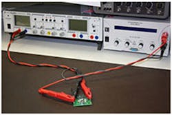
Second, minimization of the current path area further reduces the parasitic inductance. An obvious way to accomplish this is to twist the lines. This results in the current path area only depending on the line length and the thickness of the stranded-wire sheath. Figure 2 shows the connection of a test voltage converter with twisted connection lines for reduced parasitic-line inductances.
2. In a practical operational setup, it’s important to use short twisted cables to minimize parasitic inductances even though the current flow is mostly dc.
In power supplies based on switching regulators, line-ac voltage levels are found on both the input side and on the output side. Depending on the circuit topology, a pulsed current can occur at the input side as, for example, in step-down converters (buck controllers). The startup behavior and operation under load transients must also be tested. Under these operating conditions, the connection lines in the test setup also carry ac.
Adding a Local Energy-Storage Device on the Input
If a power supply is tested with respect to how quickly it can respond to load transients, sufficient energy must be available at the design under test (DUT). The energy source on the input side of the DUT should not be the limiting factor. To ensure that this isn’t the case, placement of a larger bulk capacitor at the voltage supply input is recommended (shown in green in Figure 1). It ensures that load transient tests can be performed properly.
However, it’s important to ensure that actual use of the power supply is subject to very specific conditions. The effect of the energy-storage device at the input must be well understood so that the input capacitor for the power supply can be sized correctly.
There’s another aspect of the bulk capacitor to consider. If voltage transients need to be applied at the input of the power supply to test the resulting behavior, the bulk capacitor will significantly slow down the voltage transients seen by the circuit under test. Therefore, the bulk capacitor should be removed for these tests.
In summary, a few things must be considered in apparently simple tasks related to the design and test of the power supply. Over time, experienced power-supply engineers have developed methods that optimize the evaluation of circuits. Power lines to the circuit under test, as well as power lines away from the circuit under test, need to be treated as ac circuits. Thus, these cables need to be short and direct to reduce their parasitic inductance. Doing so requires only a little more effort, yet will help ensure that the test results come close to what we actually intend to test. If influences from the test setup are reduced, the rest results will have increased validity.
Frederik Dostal, who joined Analog Devices in 2009, works as a power-management technical expert for Europe.


