This article is part of the TechXchange: Delving into EMI, EMC and Noise and Power Supply Design
What You'll Learn
- The effects of ripple and noise and the importance of filtering
- Proper bypass design
- Adding post-regulation
Noise is a constant problem in power-supply design. While there are FCC limits on the electromagnetic interference (EMI) radiating out into the air as well as the conducted noise that your design injects back into its input, your first noise problem is getting the noise low enough in your outputs.
The Effects of Ripple and Noise
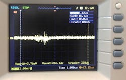
Some engineers make a distinction between output ripple and output noise. Both phenomena are an unwanted signal superimposed on the pure perfect dc output you want (Fig. 1). The source of ripple is the periodic input frequency, as well as the switching frequency of the control chip. An ac-dc supply will have a 50-, 60-, or perhaps 400-Hz input frequency. No matter how good the switching chip you use, a little of this frequency will bleed though the switching circuit.
The amount of input-referred ripple will be governed by the line regulation of your design. This is a similar concept to power-supply rejection ratio (PSRR)—how much of the input signal a linear regulator lets pass to the output. It’s not solely a function of the control chip as much as the workings of the entire circuit.
A PSRR of 60 dB means any deviation at the input will be attenuated by 1000 at the output. A primary way to improve line regulation is to increase the gain of the control circuit. The higher the gain of the control loop, the smaller the error at the output; input ripple is just another error that must be dealt with by the loop. You can also use larger input capacitors, which will reduce the ripple on your dc input bus, so the PSRR of the control loop will apply to a smaller deviation.
On top of any inherent ripple in the output will be random noise generated by the control chip voltage reference and all other sources of thermal, shot, and flicker noise. There are three common ways to deal with this noise, that often help with ripple as well:
Filtering in Power Supply Design
You can use a filter to remove noise from a power supply just like you use filters to remove noise from a signal. Indeed, you can consider the output capacitors part of a filter that reacts against the output impedance of the power-supply circuit. Increasing the value of the output capacitance will reduce noise.
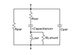
Be aware that capacitors have both an equivalent series resistance (ESR) and an equivalent series inductance (ESL) (Fig. 2). Selecting capacitors with lower ESR and ESL will lower noise, but be careful, some power-supply circuits use the ESR to provide the error signal for feedback. If you reduce it radically, say, by replacing electrolytic capacitors with ceramic ones, you may make your power supply unstable.
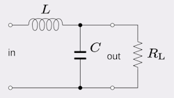
In addition to the natural output capacitance of the power supply, you might add a series inductor and another filter capacitor to further reduce output noise (Fig. 3). The inductor passes dc current with negligible loss, while providing a high-frequency impedance that the capacitor can react against to filter out the noise. In essence, you’re increasing the high-frequency output impedance of the supply so that you can more effectively filter it with smaller capacitors.
The problem with adding LC circuits is that they have a natural resonant frequency. Thus, it may make your supply unstable or produce unacceptable ringing after transient load changes. If the supply is providing low currents, you may be able to use a resistor instead of an inductor. That will create a dc loss term, but the resistor also adds damping to your output filter.
One filter useful for switching spikes and other high-frequency output noise are ferrite beads. The magnetic coupling with the output trace or wire and the bead will attenuate the noise. Another output noise source might be electromagnetic coupling from the outside world. Here you use shielding to protect the power-supply circuit from external influences.
Also note that your circuit board traces have inductance, and you might need to tailor that with power planes and trace widths. Using twisted-pair wiring is a good way to reduce inductance in order to prevent ringing and overshoot spikes. Adding any filter may increase the startup time and transient response of your system. If you’re cycling power to take a measurement and then shutting down, you have to trade off the filtering effectiveness with your startup time requirement.
Proper Bypassing
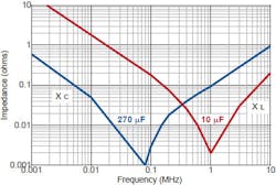
Perhaps less obvious, you can also reduce noise via proper bypassing of the control chips in your power-supply design. Bypassing the chips that being fed by the power supply will not reduce the noise at the supply, but it will be reduced at the power pins of the chips. When you bypass the chips in your power-supply circuit, use the normal guidelines of putting the capacitor close to the power pins and employ ceramic capacitors, preferably surface-mount, which have low ESR and ESL. Note that the capacitor’s physical size will dictate its effectiveness as much as its value (Fig. 4).
Including Post-regulation in a Design
A good, but expensive, way to reduce power-supply noise is to put a second low-noise regulator on the power-supply output. This often involves a low-dropout (LDO) linear regulator. It will reduce any output ripple by an order of magnitude or more. Better yet, you can add an RC or LC filter after the LDO to reduce noise even further. The noise of a linear regular is often expressed as an RMS value over one or more frequency ranges. If you need a very precise and low-drift power source, you can use a reference chip instead of an LDO regulator.
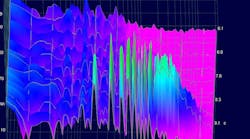
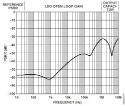
One thing to keep in mind is the frequency ranges that experience noise. Amplifiers also have power-supply rejection, and this rejection drops off significantly at high frequencies. Unfortunately, the PSRR of linear regulators also gets much worse at high frequencies (Fig. 5).
However, such high-frequency noise is much easier to remove with LC or RC filtering, so all is not lost. The holistic approach is to remove noise at the input to the switcher, then bypass and make sure your switching IC chip is low noise. After that, pick a low-noise LDO linear regulator, so that you can then add an output filter. You should examine the PSRR of the chips you’re powering and intersect that with the PSRR of the linear regulator to remove as much noise as you can over the frequency bandwidth of your circuit. Then design the filter to remove sufficient high-frequency noise to achieve your signal-path noise goals.
Bonus
Filtering, bypass, and post-regulation are the three primary ways to reduce power-supply noise, but there are some less-used techniques. One is to use a battery to power your circuitry. Batteries are a very low noise power source compared to switching or even linear converters.
Another trick is available if you only need infrequent measurements. You can disable the switching regulator momentarily and use large hold-up capacitors to power your circuit while taking the measurement. A final trick is to synchronize the switch regulator with the acquisition of the measurement, so that it occurs at the same point in the ripple and other periodic noise of the supply. This is similar to synchronizing multiple switching power supplies. In that case, you’re trying to eliminate any beat frequency created by different switching frequencies.
No matter whether you’re plagued with ripple, noise, or beat frequencies, these techniques will allow you to reduce the noise of your power system to levels low enough for your needs. When you get to 18-and 24-bit measurements and digital-to-analog (DAC) conversions, getting the power-supply rails as clean as possible is essential to obtain the available performance out of the ICs you’re using.
Read more articles like this at the TechXchange: Delving into EMI, EMC and Noise and Power Supply Design
Originally published on Nov. 13, 2019
