Download this article in PDF format.
Transformers are static electrical devices with no moving parts, transforming electrical power from one voltage and current setting to another. The frequency of the electrical current remains constant.
Transformers are classified by their function, which is either step up or step down. Step-up transformers increase the voltage of the incoming current, while step-down transformers decrease the incoming current’s voltage. The incoming voltage is referred to as the primary voltage, while the outgoing stream is referred to as secondary.
Generally, step-up transformers are located at power generation plants, stepping up the voltage flowing from the power plant to long-distance distribution networks. Step-down transformers, on the other hand, decrease the voltage of power streams received at the local distribution level. The long-distance stream is first stepped down to a level acceptable for local distribution, and then stepped down again at each consumer node (residential homes and offices).
The Necessity of Transformers
When transmitting power over both long and short distances, there are inherent losses in the system. These losses are of greater magnitude when the current is higher (at lower voltage) than at a low current. For this reason, long-distance transmission necessitates that electricity has high voltage and low current. High voltages aren’t safe for consumers, though, and aren’t suitable for most electrical appliances. Consumer appliances are generally rated at 220 V.
Transformers convert electricity between the high-voltage, low-current needed for long-distance distribution, and the low-voltage, high-current needed for consumer use.
As an aside, power transmission lines are generally manufactured from copper to minimize the losses associated with transmission. Copper offers the lowest electrical resistance of all conductive materials.
Step-Down Transformer Application
Power-generation plants produce electricity at 20 kV, which is then stepped up to 440 kV for long-distance distribution. When received at a local distribution station, the voltage is reduced to 11 kV using a step-down transformer. From here, for distribution to individual consumers, another step-down transformer reduces the voltage to the standard 220 V suitable for consumer use.
Household voltage is 220 V in most areas. However, household outlets operate at 110 or 120 V in the United States and neighboring countries. Connecting a 220-V device to a 110-V outlet may damage the device. Fortunately, inexpensive adapters (Fig. 1) are readily accessible to fully solve the problem. They’re sold for less than $20 in most electronics shops. Many of these European-made devices specifically state that they can be used in the United States.
Transformer Operation
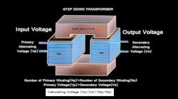
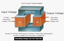
Transformers work on the principle of mutual induction. A changing magnetic field in one loop of wire induces an electromotive force (EMF) in an adjacent loop of wire, inductively coupled to the first. In very basic terms, a transformer consists of two coils of wire with high mutual inductance. These coils are electrically separated while they share a common magnetic circuit (Fig. 2).
For a step-down transformer, the second coil has fewer windings than the first, allowing for a decrease in voltage in the exiting electrical stream.
The primary winding, which is the first set of coils, connects to an alternating-current voltage source, or primary voltage inflow. The secondary coil connects to the load, or secondary voltage outflow, distributing the electrical power away from the transformer.
The alternating current flowing in at the primary voltage creates an alternating magnetic flux. This induces a similar current in the secondary coil, creating a secondary voltage. Here, the decreased number of windings in the secondary coil effectively reduces the resultant voltage, hence “stepping down” the voltage to a lower value while maintaining a constant frequency.
Note that while the voltage decreases, the current increases for the frequency to remain constant. For this reason, the secondary coil in step-down transformers usually has a larger-gauge wire for the secondary coil than for the primary coil. Since the primary voltage’s current is low, the wiring of the primary coil doesn’t require an overly thick wire. Conversely, the increased current flowing through the secondary coil necessitates an increase in wire thickness. If the wire in the secondary coil is too thin, the wire melts due to the resistive heat build-up, causing catastrophic failure.
Alternating the Flow Direction
It’s possible to use both step-up and step-down transformers backward. By switching the inflow and outflow, the direction of the electrical stream is reversed. In this manner, a step-up transformer can carry out the function of a step-down transformer and vice versa.
Manufacturing Considerations
Transformers are an expensive but essential aspect of the electricity supply chain. A large amount of capital expenditure is needed to acquire transformers, and it’s expected that they last for the entire forecast lifespan. In reality, though, these transformers usually fail about halfway through their expected lifespan. Windings, tap changers, and bushings in ill repair are often the primary cause.
However, inadequate maintenance plans aren’t solely to blame. Transformers are often mismatched to their intended usage conditions, placing unnecessary strain on the device once in use. Even though transformers are entirely static, with no moving parts, the intensity of the current flowing through the wire coils causes wear on the coils themselves. The same is true for the tap changers and bushings. Over time, the integrity of these materials is compromised, failing either mildly or catastrophically.
To prevent this premature failure, transformers must be specified with care. Once installed, commissioning should be done with care, too. Operating conditions must be meticulously controlled, and maintenance plans carried out regularly and thoroughly. With these provisions in place, transformers are likely to provide optimum performance for the entirety of their forecast lifespan.
Core
Furthermore, be judicious when choosing the grade of material used for the transformer core. While a higher-grade material is generally more expensive, it usually results in a longer expected lifespan. Match the grade of material to the normal conditions of use and the transformer’s desired lifespan.
Windings
Choose the type of metal used in the transformer’s windings with care. The aim here is to minimize resistance in the wires while maximizing electrical conduction. Copper is generally the best choice in this case, although it’s generally more expensive than aluminum, which is the alternative.
In the long-term, copper generally is the most cost-effective option, since it offers less resistance to electrical current than the alternative materials. This decreased resistance results in fewer electricity losses, increasing the long-term efficiency of the equipment. An added benefit is the decreased heat build-up in the system since electrical resistance generates heat when using alternative materials.
It’s important to understand the physical arrangement of the coils. This arrangement should match the expected operating conditions.
Insulation
Insulation is critical to the proper functioning of a transformer as well as the safety of personnel on-site. Match this to the expected operating conditions, ensuring the optimal selection of the insulating material and configuration.
Conclusion
Transformers are essential to the effective functioning of the national power grid. These devices allow electrical power to be converted to the correct voltage to current ratios for both long-distance transmission and local distribution. Due to their cost, transformer should be chosen with care. Correct operation and adequate maintenance prolong the transformer unit’s expected lifespan.
Kiran Daware is a Junior Electrical Engineer at Nicore India Pvt. Ltd.


