Understanding EMI Filters: The Bare Essentials
This article is part of the TechXchange: Delving into EMI, EMC and Noise
Members can download this article in PDF format.
What you'll learn:
- Rules and standards regarding noise and EMI.
- The basic facts about, and causal factors of, EMI.
- How to implement an EMI filter in a design.
Before we discuss electromagnetic-interference (EMI) filter basic information, let’s first understand why we need EMI filters in electronics.
One important reason designers need EMI filters is that regulatory agency requirements for RF/wireless devices for use in the USA (FCC), Canada (IC), Europe (CE), and many other countries dictate that radiated and conducted emissions be constrained below specified limits and must pass immunity/transient requirements. Designers need to understand that EMI filters will help in meeting immunity and fast transient requirements as well as radiated emissions to achieve a robust design.
Regulatory Agency Rules
The electronic industry regulatory agencies have determined rules to suppress noise generated from electronic devices to a reasonable level. These agencies make sure that electronic devices will operate correctly under a certain noise level so that we can use those devices with adequate security. These rules are known as noise regulations.
In today’s environment, so many more electronic devices are surrounding us than ever before. The number of electronic devices will continue to grow with new technology advances.
In an electronic device, which is considered a “source” of noise, the occurrence of that noise is called emission or emission of noise. In contrast, if an electronic device is considered a “victim” of noise, the tolerance to noise is called immunity or noise tolerance.
EMI Filters Also Must Adhere to Safety Standards
In a safe design, inductor temperature rise is usually measured. The power mains operation will control the minimum electrical spacing between line, neutral, and ground. These efforts will reduce the risk of fire and electrical shock.
Each capacitor will need to be safety-certified, depending on their position in the circuit. Special capacitors have to be used across the power mains input terminals, as will capacitors from the ac circuit to ground.
The EMI Suppression Filter
The EMI filter is an electronic component that provides electromagnetic noise suppression for electronic devices. This filter is typically used together with shields and other types of protection. EMI filters only extract and remove offending noise components that can cause electromagnetic noise from electric currents that conduct through electrical wiring.
What Exactly is EMI, Though?
EMI is simply noise interference caused by external electromagnetic waves. EMI can lead to the performance degradation of any electrical equipment design within range by inducing unwanted currents and voltages in its circuitry.
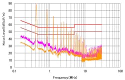
EMI has two major components: conducted EMI and radiated EMI. Conducted EMI is coupled via conductions through parasitic impedances, power connections, and ground connections. Radiated EMI, however, is coupled through radio transmissions. It has been demonstrated that keeping the conducted differential performance in check above 30 MHz also will help meet the separately tested radiated EMI requirements (Fig. 1).
Noise is coupled to a susceptible system via the following mechanisms:
- At low frequencies, the coupling is caused by conduction.
- At mid-frequencies, the electric and magnetic fields are the mechanisms for coupling.
- At high frequencies, the coupling is from radiation.
PCs, mobile phones, and other electronic devices typically can emit unwanted noise that may interfere with the performance of other electronic devices within their range.
Note: Don’t confuse electromagnetic compatibility (EMC) with EMI. EMC is an electrical system’s ability to perform its functions in the presence of EMI generated, either internally or externally, from a nearby system.
Noise Interference within a System
Even in the absence of external noise sources, outside of an electronic device, the inside circuits may cause interference with other circuits in that system. This is known as “intra-system EMI.” An example is digital circuitry emitting noise that’s induced into a wireless circuit within a smartphone, which may have difficulty receiving/transmitting wireless signals to and from a local 5G base station. Another example would be a radio that might also be affected by a motor nearby.
Circuits of ever-higher sophistication are laid out in close proximity to other circuitry to reduce the form factor of the overall design. On-board sensitive components may be placed close to power-management circuitry with large voltages and currents. This kind of layout could lead to some circuitry interfering electromagnetically with nearby sensitive circuitry. Design layouts must achieve an adequate density of components while being sensitive to EMI interference to other, more susceptible components.
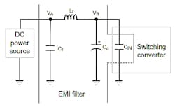
One of the most common circuits in modern electronic systems is the switch-mode power supply (SMPS), which offers a huge efficiency improvement over a linear regulator in most applications. However, that high-efficiency bonus comes with a downside: switching power FETs on and off in a SMPS becomes a major source of EMI. One type of EMI filter for a SMPS is a differential-mode architecture (Fig. 2).
Using an EMI Filter in an Electronic Product
First, let’s look at the basic electrical filter. A filter may be analog, digital, active, or passive in an electronic system. A filter that prevents noise in a system will control offending frequencies that are undesirable to the system. Filters receive a signal at their input and produce an output that’s modified by the internal circuitry to remove unwanted noise from going to the system. Typically, the filter input may be an ac or mains power signal.
Other filter types may be designed to remove other “noisy” offenders in the input signal. We don’t want the EMI filter to compromise efficiency or power density in the power supply. This will be discussed in later articles.
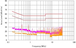
The EMI filter will effectively filter out a specific frequency in the power line or any outside offending frequency to obtain a relevant power signal of a specific frequency or eliminate the power signal above a specific frequency point. Essentially, an EMI filter is an electrical device/circuit that will help mitigate the high-frequency electromagnetic noise present on the power lines as well as on signal lines (Fig. 3).
EMI filters may be classified as low pass, high pass, bandpass, or band reject. EMI filters are usually designed with passive components like capacitors and inductors configured in LC form or even in more complex architectures.
Inductors, in an EMI filter, enable low frequency or even dc signals to pass through but will block unwanted higher frequency components. The capacitors will typically direct high-frequency noise through a low-impedance path back to the power-supply ground or system ground.
Conclusion
When a new product design is released to the world of electronics, it must pass specific EMI tests to meet local standards for that particular product type. In this article, EMI is described and EMI suppression filters are defined. EMI noise inside a system is discussed, and the example of switching power supplies are covered as possible offenders there. Finally, using an EMI filter in an electronic product is covered at a basic level.
Read more articles like this at the TechXchange: Delving into EMI, EMC and Noise


