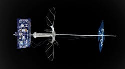
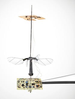
This is the stuff of science fiction turned fact, no doubt about it: The world’s smallest and lightest insect-like aerial vehicle had a successful test and realized brief but sustained, solo, untethered flight (Fig. 1). Called “Robobee” and developed by a multidisciplinary team at the Harvard University Microrobotics Laboratory, it weighs 259 milligrams (including on-board solar cells and electronics) and uses about 120 milliwatts of power. The “wingspan” is about 3.5 cm and overall height is about 6 cm. (Note that “insect- like” is generally considered as having mass under 500 milligrams and wingspan less than 5 cm.)
1. The Robobee, a centimeter-sized aerial vehicle, flies using slowly flapping wings. The solar cells that power the vehicle are positioned above the wing system and the electronics are located below (the vehicle is shown being held by tweezers).
This physical arrangement of the microscale aerial vehicle represents about six years of work as a major upgrade to its predecessor, which required a power cord and thus wasn’t untethered. “When you see engineering in movies, if something doesn’t work, people hack at it once or twice and suddenly it works. Real science isn’t like that,” observed team member and graduate student Elizabeth Farrell Helbling, (Ph.D. ’19).
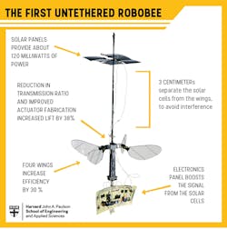
The most obvious change was the increase to four wings from two (30% efficiency improvement), along with less-visible changes to the actuator and transmission ratio (38% improvement) to make the vehicle more efficient and give it more lift (Fig. 2). The solar cells are set about 3 cm above the flapping wings to avoid shading.
2. This schematic of the Robobee shows the basic arrangement of its major functional blocks and improvements.
These and other changes finally allowed untethered, self-powered flight for the first time. The fascinating, slightly hypnotic 90-second video below captures the gracefulness of the flapping wings. (Note that the tether seen in the video is only a passive Kevlar safety harness needed to minimize damage to the Robobee if it crashes and doesn’t carry power or data.)
Professor Robert Wood of the Harvard School Engineering and Applied Sciences (SEAS), also a faculty member of Harvard’s Wyss Institute and principle investigator of the Robobee project, noted that “This is a result several decades in the making… powering flight is something of a Catch-22 as the tradeoff between mass and power becomes extremely problematic at small scales where flight is inherently inefficient.”
The peak lift was 370 mg via the four wings, which are driven by two alumina-reinforced piezoelectric actuators. The peak lift-to-weight ratio of 4.1 to 1 demonstrated greater thrust per “muscle” mass than typical biological counterparts. The wings are constructed with a laser-machining process, using an internally developed manufacturing tool that has evolved and matured to become a major resource for the fabrication of small-scale robotics.
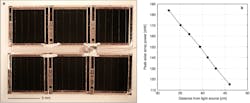
3. Shown is a six-cell photovoltaic array (a). The plot reveals the power obtained from this solar array at varying distances from the light source (the measurement precision is approximately ±5 mW). The power at 1 Sun is approximately 46 mW.
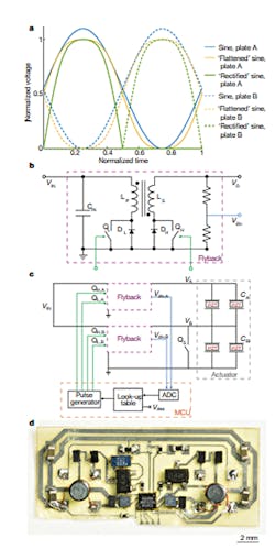
The six solar cells—the smallest commercially available—weigh 10 mg each and deliver 0.76 mW/mg of power when the sun is at full intensity (Fig. 3). However, even full sunlight isn’t enough for the Robobee, which needs the luminous intensity of about three Suns, so testing was done indoors with halogen lights. The low-voltage output of the solar array must be transformed into 200-V/170-Hz pulses for the piezoelectric actuators by a dc-dc subsystem (Fig. 4).
4. Drive electronics details: Three drive waveforms that result in identical flapping kinematics (a). Circuit diagram of a bidirectional flyback converter—VIN is the input voltage, CIN is the input capacitor, QL is the low-side switch, DL is the low-side diode, LP is the primary winding of the transformer, LS is the secondary winding of the transformer, QH is the high-side switch, DH is the high-side diode, and VO is the output voltage (b). Full circuit diagram, including two bidirectional flyback converters from b (purple), driving two piezoelectric bimorphs (labelled ‘Actuator’), one ADC in the MCU (orange) monitors the output voltage of plate A (VA) or plate B (VB) using the corresponding low voltages Vdiv,A or Vdiv,B, respectively (c). A lookup table compares the result to a desired voltage Vdes and generates a corresponding pulse to switches QH,A, QL,A, QH,B, and QL,B, while additional switch QS electrically clamps plate B to ground when plate A is driven. CA and CB are the capacitances of the actuator plates. The circuit of (c) as built (d).
For powered flight, analysis of power-to-weight ratio is obviously critical. The table lists the bill of materials (BOM) for the supply and the mass of each component.
Their paper, “Untethered flight of an insect-sized flapping-wing microscale aerial vehicle,” published in Nature (an unlocked version is posted here), provides in-depth details, charts, graphs, performance and tradeoff analyses, and useful references, along with 10 more videos. There’s also some less-technical discussion and background in Nature News and Views, “Flight of the RoboBee.” The design, execution, and flight show how compromise among competing interests of weight, power, control, strength, resilience, and even cost can lead to a successful, truly unique project.
