Members can download this article in PDF format.
To interconnect automotive engine control units (ECUs), you can choose from among several in-vehicle network buses, ranging from the Local Interconnect Network (LIN) to Ethernet. Among the options, the Controller Area Network (CAN) bus remains popular because it’s easy to use, offers good common-mode noise rejection, and supports priority-based messaging and bitwise arbitration.
Sponsored Resources:
- How SIC unlocks the real potential of CAN-FD transceivers
- Designing with CAN SIC transceivers
- TI Precision Labs - CAN/LIN/SBC
In addition, the CAN bus provides error detection and recovery, and you can easily add nodes to an existing CAN bus. Beyond the automotive space, it finds use in a host of industrial applications.
CAN Evolution
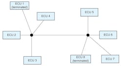
CAN has matured greatly since its inception in the 1980s. The initial standard specified eight bytes of payload data and a data rate of 1 Mb/s. CAN-FD (for Flexible Data Rate) emerged in the mid-2010s, expanding the payload to 64 bits and the maximum signaling rate to 5 Mbps. However, in complex networks such as those employing star topologies (Fig. 1), CAN-FD transceivers rated at 5 Mb/s must be throttled back to 2 Mb/s because of the ringing caused by unterminated stubs.
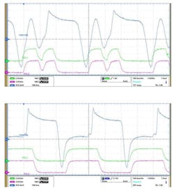
As shown in Figure 2 on the left, ringing can exceed the 900-mV dominant threshold of a CAN receiver and fall below its 500-mV recessive threshold. This ultimately causes glitches in the receive-data (RXD) signal.
To overcome this 2-Mb/s limitation, CAN transceivers can incorporate a signal-improvement capability (SIC) as defined in the CAN in Automation (CiA) 601-4 specification. CiA 601-4-compliant transceivers have tighter bit-timing symmetry and loop-delay specifications than standard CAN transceivers, enabling them to operate at 5 Mb/s and beyond even in complex network topologies without RXD glitches (Fig. 2, right).
SIC makes use of differences between dominant and recessive CAN-bus states. The recessive-to-dominant CAN-bus signal edge is usually clean. In addition, the CAN transceiver’s differential transmitter output impedance during the dominant phase is approximately 50 Ω, closely matching the network characteristic impedance.
However, for a regular CAN-FD transceiver, the differential output impedance suddenly goes to 60 kW at the dominant-to-recessive edge. This results in an impedance mismatch that causes reflections and ringing.
To minimize reflections, transmitter-based SIC detects the dominant-to-recessive edge and activates ringing-suppression circuitry for the duration of an active recessive phase, while the transmitter output impedance remains low (about 100 Ω). As a result, the recessive data bit remains clean at the data sampling point. After the data is sampled, the active recessive phase ends and the transceiver enters a passive recessive phase. At this stage, the driver output impedance rises to approximately 60 kΩ, as was the case for the standard CAN-FD transceiver.
CAN SIC Products
Texas Instruments offers two CAN SIC transceivers. The TCAN1462-Q1 8-pin CAN SIC transceiver supports low-power standby and optional 1.8-, 3.3-, or 5-V I/O for communication with your microcontroller of choice. It offers standby-mode support and is pin-to-pin compatible with previous generations of 8-pin CAN transceivers, including the TI TCAN1044A-Q1 family.
The 14-pin TCAN1463-Q1 CAN SIC transceiver supports sleep, wake, and inhibit functionality. It includes internal logic-level translation to allow for interfacing directly to 1.8-, 2.5-, 3.3-, or 5-V controllers. The device also includes features such as undervoltage detection and thermal shutdown. It’s pin-to-pin compatible with traditional 14-pin CAN transceivers, including TI’s TCAN1043A-Q1.
Both the TCAN1462-Q1 and TCAN1463-Q1 are AEC-Q100-qualified devices, offer ±58-V bus fault protection, and come in SOIC, ST-23-THN, and VSON packages. Evaluation boards are available for each device as well.
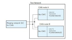
Texas Instruments has conducted an experiment to demonstrate the ringing-suppression functionality of the TCAN1462-Q1. The test setup (Fig. 3) employs the TCAN1462 for CAN node A and a TCAN1044A regular CAN-FD transceiver for node B. A ringing network emulates a complex star topology.
As shown in Figure 4, the CAN bus and RXD signals exhibit considerable ringing when the standard CAN-FD transceiver drives the bus, but the signals look clean when using the CAN SIC transceiver.
Online Training
To help you get started on CAN and other interface designs, Texas Instruments offers its TI Precision Labs (TIPL) comprehensive online classroom. The TIPL CAN and LIN Series describes how to design with CAN and LIN transceivers and multifunction system basis chips (SBCs). It covers CAN and LIN physical-layer electrical signaling characteristics as well as their frame structures and data-communications protocols.
An introductory video in the series describes how CAN transceivers communicate over the CAN bus with an emphasis on automotive applications in relation to the ISO 11898 standard. That six-part standard describes the data-link layer and physical signaling, high-speed medium access, a low-speed fault-tolerant medium-dependent interface, time-triggered communication, a high-speed medium-access unit with a low-power mode, and a high-speed medium-access unit with a selective-wake mode.
The second video in the series focuses on the CAN physical layer, discussing electrical transmission characteristics and hardware requirements. The third video describes how information is encoded and passed between devices on the CAN bus using ISO 11898, covering arbitration, frame structure, and bit stuffing. The final video provides an overview of LIN for automotive applications, delving into the physical layer and frame structure.
Conclusion
CAN SIC transceivers offer significant system benefits over regular CAN-FD transceivers. Improved bit-timing symmetry enables more margin for network effects that can degrade CAN signals, and low loop delay (190 ns max, compared to 255 ns max for CAN-FD transceivers) helps extend maximum network length.
CAN SIC is backwards-compatible with CAN-FD, and you can implement it without the need for design changes at the physical or application layer. Furthermore, the technology serves a variety of applications, from increasing a camera’s frame rate to improving an automotive infotainment system.
Sponsored Resources:


