Position Sensors for Optical Encoders Enhance Resolution and Accuracy
Analog and digital optoelectronic sensors combine an LED and an optoelectronic integrated circuit in a compact package to enable optical encoders to provide absolute or incremental position detection in a variety of industrial applications.
Position detection is an essential technology for industrial applications ranging from collaborative robots to semiconductor manufacturing equipment. Methods ranging from video-imaging analysis to magnetic detection can provide position sensing, but optical methods provide key advantages. They are immune to the effects of stray magnetic fields, and since they are compact, they can be located close to motors or other components of the equipment in which they are used.
Position sensing and reporting
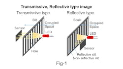
Optical sensors can take two approaches to position sensing: transmissive and reflective. As shown in Figure 1 left, with transmissive sensing, light from an LED penetrates a series of slits on a scale to reach a photosensor on the opposite side. With reflective sensing, as shown in Figure 1 right, the LED and sensor are located on the same side of the scale, and light from the LED reaches the sensor when reflected from the scale’s reflective slits, which alternate with non-reflective slits.
Optical sensors can also take two approaches to how they report position. With the incremental approach, a sensor can indicate the amount of rotation or linear movement, but it cannot report absolute position information without some method of determining the initial position at startup. In contrast, absolute position encoders can always report the exact position information as soon as power is turned on.
Analog and digital outputs
Optical sensors can provide either digital or analog outputs. With digital outputs, relative position is determined by counting pulses, and pulse width determines the resolution. Digital versions serve in manual focusing for mirrorless and remote cameras as well as in brushless motors, high-resolution stepper motors, and related applications.
Analog versions generate sine and cosine wave outputs, with arctangent calculations extracting position information from the output signals. The resolution depends on analog output distortion, and high-precision analog sensors can achieve resolution of 1 µm or less. The analog versions typically find use in linear (straight-line) detection and can provide µm orders of resolution. Applications include camera lens position detection, collaborative robots, and linear actuators.
Compact sensor families
Nisshinbo Micro Devices Inc. offers a variety of small, thin digital and analog optical position sensors, which it has developed by marrying its circuit-design skills with its device packaging technology. Currently, the company is focusing on expanding its lineup of incremental optical reflective position sensors.
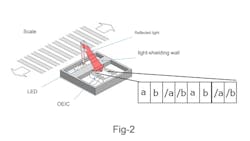
Digital examples include members of the company’s NJL5820/21/22R family, each of which combines a near-infrared LED and an optoelectronic integrated circuit (OEIC). The OEIC can handle both optical and electrical signals. It includes a photodiode that converts light to an electrical signal, plus a circuit that amplifies the signal. A light-shielding wall between the LED and the OEIC provides optical isolation (Figure 2).
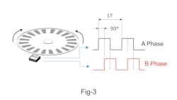
In operation, as a scale with an alternating reflective and non-reflective pattern affixed to a moving part moves past the OEIC, the image the OEIC receives changes. In response to these changes, the OEIC produces a two-phase (A and B) pulse signal with a phase difference of 90 degrees that matches the alternating pattern period (Figure 3). A microcontroller unit (MCU) can detect these pulses and derive the position, distance, direction, and speed of the moving part. Members of the NJL5820/21/22R family have position detection resolutions of 50.8, 150, and 180 lines per inch (LPI), respectively.
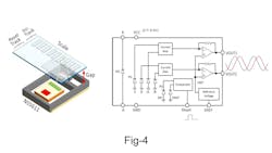
Analog examples include Nisshinbo’s NS5611, which can form the basis of a reflective incremental optical encoder. Similar to the NJL5820/21/22R, the NS5611 package includes a near-infrared LED and an OEIC. As a reflective scale moves past the sensor (Figure 4, left), the device generates a two-phase analog output with a phase angle of 90 degrees at 140 µm per period (red and blue waveforms, Figure 4, right). An analog-to-digital converter (ADC) can digitize these signals, and an MCU can use the digital output to calculate the distance moved.
Encoder design considerations
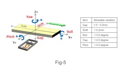
Several design aspects must be considered when integrating an optical position sensor into an optical encoder. In general, high-resolution position sensors are not suitable for use with flexible printed-circuit materials because any flexing alters the positional relationship between the scale and the sensor, affecting resolution. However, the NS5611’s robust design allows it to tolerate variations in the scale’s position relative to the device. Figure 5 shows allowable variations with respect to the gap between the scale and the sensor, the scale shift, and the scale roll, pitch, and yaw.
Conclusion
Optical position-detection sensors are available in a variety of transmissive and reflective analog and digital configurations. Nisshinbo is applying its decades of semiconductor component development experience to expand its offering of analog and digital reflective optoelectronic position sensors to provide additional options and high levels of resolution and accuracy for use in optical-encoder designs.
Captions
Figure 1. Optical position sensors can employ transmissive (left) or reflective (right) methods.
Figure 2. A light-shielding wall isolates the LED from the OEIC.
Figure 3. In response to changing light patterns, a digital-output OEIC produces a two-phase pulse signal.
Figure 4. As a scale moves past the NS5611 (left), the sensor generates a two-phase analog output (right).
Figure 5. The NS5611 can tolerate positional variations relative to the scale.

