One of the backbones to the success of any automated process is the accuracy to which one can detect and measure the various elements involved. Whether the process requires precise measurement and accuracy involving a liquid, solid, or empty space, understanding every part of the process is critical.
Strategic implementation of various sensors makes it possible to optimize a process from the start and equips an operator with the information needed to constantly be aware of everything happening in a line. He or she can then make smart, informed decisions regarding adjustments that may need to take place.
To start the decision-making process of choosing the right sensor for a specific application, a few questions should be considered:
- What type of object needs detection?
- What type of environment is it?
- What is the required sensing distance?
- What does the response frequency need to be?
- What type of output is needed?
The answers to these questions will guide the decision as to which type of sensor or specific mix will work best.
Proximity Sensors
Proximity sensors are designed to do exactly what the name implies—detect the proximity between one element and another. There are two main types of proximity sensors: inductive and capacitance. Inductive proximity sensors are designed to detect matter and capacitance proximity sensors are better used for detecting liquid.
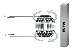
Inductive proximity sensors contain a wire wrapped into a coil several times. When a current is applied, a strong magnetic field occurs in the direction of the thick arrows illustrated in Figure 1. When metal comes into the proximity sensor’s magnetic field, it’s ultimately detected by the sensor.
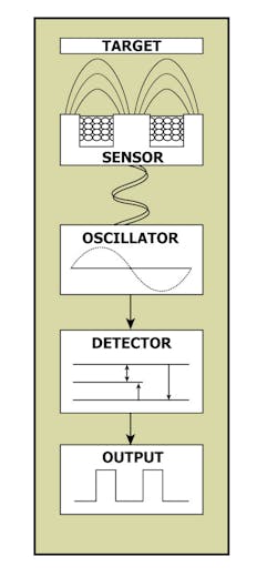
As shown in Figure 2, an inductive proximity sensor contains four main components: sensor head, oscillator circuit, detector circuit and the output circuit.
The coil on the sensor head radiates an electromagnetic field, and the core of the sensor head directs the field to the front of the sensor. The oscillator circuit creates a high-frequency, symmetrical, oscillating electromagnetic field that radiates out from the ferrite core and coil assembly at the sensing face.
When a ferrous material enters the magnetic field, small currents known as eddy currents are induced on the metal’s surface. These currents represent a power loss with the circuit and cause a loss of amplitude in the oscillations. The detector circuit will detect changes in the amplitude of oscillation and send signals to switch the output on or off. When the metal target is removed from the range, the oscillator will return the magnetic field of the sensor to its typical amplitude. If the sensor has a “normally open” configuration, it will provide an “ON” output when the target enters the sensing zone.
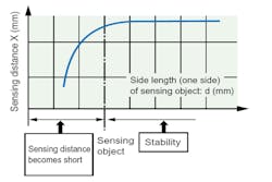
The distance at which an element can be detected depends on the material of the object. In general, if the detection object is a non-magnetic metal, the detection distance is less. Furthermore, if the object is smaller than the standard test object, the detection distance also decreases. One should design the setup for an object size that’s greater than the standard test object size from the graph in Figure 3.
The thickness of magnetic metal must be 1 mm or greater. If the coating is too thin and not conductive, detection isn’t possible. In addition, if the object is plated, the detection distance will change.
A few other factors could affect the detection distance. The existence of a metal object (other than the detection object) near the surface of the proximity switch could influence the detection performance, increase the activation distance, degrade temperature characteristics, and ultimately cause reset failures.
One last consideration for inductive proximity sensor design is whether to go with a shielded or unshielded style. A shielded proximity sensor has extra core materials on its perimeter and additional metal shields to limit the electromagnetic field to the front of the sensor. Alternatively, an unshielded proximity sensor has no extra shielding, resulting in a longer and wider sensing area.
Proximity capacitive sensors offer a technology that enables non-touch detection by measuring capacitance. The technology detects a change in capacitance in response to a change in surrounding materials. With this style, a capacitor contains two conductors at different potentials, separated by a dielectric material.
Another way to think of it is that a capacitive proximity sensor is an open capacitor. These sensors can detect conductive and nonconductive objects. This means they can detect liquids, plastics, glass, wood, and chemicals. They’re designed to sense through non-ferrous materials, making them the perfect solution for level sensing applications, including sight glass monitoring and level detection in liquid or powder tanks.
A capacitive sensor includes a capacitive probe, an oscillator, a signal rectifier, and an output circuit (Fig. 4).
The target will increase the surface area of the plates, thus building up the charge. As the target approaches, capacitance increases along with the oscillation amplitude. The capacitance of the probe is directly affected by the target’s size, dielectric constant, and its distance from the probe. As the size and dielectric constant of the target increases, so too does the capacitance. Furthermore, as the distance shortens between the target and probe, the more the target increases capacitance. Finally, the detector will send a signal to switch the output state when the oscillation reaches a specific level.
Like inductive proximity sensors, there are shielded and unshielded options. Shielded capacitive proximity sensors are more ideal for sensing low dielectric constant materials because of their highly concentrated electrostatic fields. However, the electrostatic field of an unshielded sensor is a bit less focused. This style is better for detecting high dielectric constant materials. Furthermore, unshielded capacity proximity sensors have longer sensing distances, and are more effective than the shielded variety in plastic sensor wells for liquid-level applications.
Fiber-Optic Sensors
If the environment and/or target being detected presents a challenge from a layout perspective, a fiber-optic sensor may be the ideal solution. Due to the way a fiber-optic sensor is designed, it can reach and detect certain areas that other sensors may not. They use a fiber cable to transmit and receive light used for sensing in a remotely mounted amplifier. This allows the sensing tip to be in these small areas or environments that may damage normal sensors, such as areas with high temperature or moisture.
These types of sensors are incredibly accurate and work well in liquid. Because there’s no electricity happening with this style of sensor, the head can be submerged in the solution. In addition, due to the fact that they don’t conduct electricity, there are more suitable applications.
Laser Measurement Sensors
This is a solution that makes the most sense when the nature of the detection requirements is such that high precision measurement is needed down to 0.5 microns. However, space and budget are often constraints for these types of sensors.
Photo-Electric Sensors
A device that can detect presence of an object by the change of light, photo-electric sensors are ideal for applications where a washdown or some other type of harsh environment exists. The light is converted to an electrical signal and the amount of the signal is then compared against threshold values. The reason these are so ideal in washdown environments is because there is no contact with the object, big distances of detection are possible, they’re free from wear, and they have a very fast response time.
One of the technologies that’s utilized with photo-electric sensors is known as time-of-flight (TOF). TOF is an imaging technology where a short pulse is emitted and the return time is measured, giving highly precise and accurate measurements.
With such a method, the distance is measured based on the elapsed time as opposed to how much incident light returns. This leads to a number of different benefits associated with TOF technology. The finish of the targets has less of an impact on detection accuracy, parts with different colors and textures are detectable, and errors are far less frequent.
Due to the nature of the technology, these types of sensors are best suited for the automotive, material handling and Food & Beverage industries.
Regardless of the application, it’s important to understand everything necessary about a given process in order to make an informed decision about how to best configure the sensor selection and placement. The key is to take advantage of the design’s benefits and ensure that the style’s disadvantages won’t negatively affect the task at hand.
Tom Trinh is the Senior Application Engineer at Valin Corp.


