Instrumentation Amp Features Tight Parameter Focus, Superior Results
Given the very credible performance of large-scale analog front-end ICs that combine signal conditioning, analog-to-digital conversion, and more, as well as availability of so many high-performance op amps and their siblings, you might think there’s little need for yet another instrumentation amplifier.
However, that reasoning is shortsighted, as there’s a never-ending demand from circuit designers for basic building-block analog components that excel in one or a few especially critical parameters. For example, instrumentation amplifiers (in-amps) provide signal conditioning for specialized, sensitive chemical and biomedical sensors where one of the top-tier parameters of concern is input bias current—even a little bit of this current can “upset” the sensor’s fragile output performance.
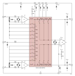
Addressing these needs is the Analog Devices LTC6373, a precision instrumentation amplifier with fully differential outputs that boasts input bias current of just 25 pA (Fig. 1). This in-amp also allows users to easily set the gain to one of seven values via a three-bit parallel interface, while the eighth setting puts the amplifier in a shutdown mode, reducing the current consumption to 220 μA.
Its closely matched internal resistor network helps it achieve excellent minimum CMRR of 103 dB at gain = 16, along with maximum offset voltage of 92 μV (maximum) at that same gain, maximum gain error of 0.012%, and gain drift of 1 ppm/°C, all important specifications for high-precision sensor signal conditioning, (Note that these numbers are minimum or maximum values rather than “typical,” an often-used but unsatisfactory qualifier for serious design for many of these applications.) Other important numbers include –3 dB bandwidth of 4 MHz; input noise density of 8 nV/√Hz; and slew rate of 12 V/μs, all at the same gain of 16.
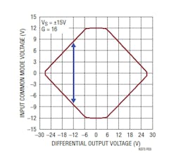
In addition, the vendor addresses a problem associated with in-amps: While they’re traditionally specified with a valid input common-mode range and an output-swing range, swing limitations are associated with internal nodes due to a combination of the gained-up differential signal and common-mode signal.
Designers can utilize the LTC6373 datasheet or a free online tool to determine the maximum input common-mode voltage limits for which a valid output is produced for each gain setting of LTC6373, using what’s called a “Diamond Plot” (Fig. 2). This is somewhat analogous to a safe-operating-area (SOA) chart for a power device.
Despite the functional simplicity of in-amps in general, the 37-page LTC6373 datasheet is also packed with dozens of tables, graphs, and histograms characterizing performance across a wide variety of static and dynamic operating conditions—another necessity for confidence in a precision design. The device operates from a supply voltage of ±4.5 to ±18 V, comes in a 12-lead, 4- × 4-mm DFN (LFCSP) package, and is fully specified over the −40 to +125°C temperature range. Pricing is about $5 each in 1000-piece orders.


