Smart DAC Devices Simplify and Improve Designs
Members can download this article in PDF format.
Engineers who need to precisely generate an analog output and control auxiliary functions typically employ a precision digital-to-analog converter (DAC) plus a combination of discrete analog components and a microcontroller (MCU). The effort required to choose the right components, write software for the MCU, and meet relevant regulatory requirements can be unnecessarily complicated when all you want to do is implement some simple, basic functions.
An alternative is to use a new type of device called a smart DAC—a factory-programmable precision DAC that has integrated nonvolatile memory (NVM), programmable state-machine logic, pulse-width-modulation (PWM) generators, and custom waveform generators.
Lighting Control
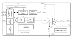
Software-based MCU designs remain useful for many primary monitoring and control applications. However, they can consume excessive resources for secondary applications or subsystems that only require auxiliary voltage margining, biasing, or trimming. Applications like lighting control (turning on a light when you open your oven or car door, for example) need only a simple sense-measure-control feedback loop. For these applications, a smart DAC such as Texas Instruments’ DAC53701 (Fig. 1) can help.
For automotive applications, smart DACs with Automotive Electronics Council-Q100 (AEC-Q100) qualification can support memory retention for 20 years at 125°C operating temperatures. One example requiring such capability is the control of daytime-running-light (DRL) LEDs, which must operate while exposed to heat and sunlight. Because LED reliability is inversely proportional to operating temperature, DRL LEDs require a thermal foldback function, which a smart DAC can implement. Smart DACs also help control tail-light animations and turn signals.
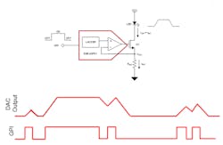
For other automotive as well as appliance and consumer-electronics lighting applications, smart DACs can produce fade-in and fade-out signals to control illumination levels based on a general-purpose input (GPI)—e.g., a high/low sensor input indicating whether a refrigerator door is open or closed. Figure 2 shows a smart DAC and LED driver circuit as well as the relationship between the GPI and DAC output, whose rise and fall responds directly to the GPI to produce a slewed LED fade-in or fade-out drive current.
In addition, smart DACs may find use in medical applications, where they can generate alarm signals for the patient-monitoring equipment used in intensive-care units. Smart DACs are able to provide preconfigured audio alarm patterns based on various trigger conditions. These alarms can continue to work even if system software fails, thereby potentially easing the medical-equipment regulatory approval process.
555 Timer Alternative
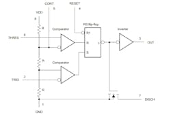
A smart DAC also can serve as an alternative to the venerable 555 timer (Fig. 3), which engineers have used for years to solve a variety of system design problems. The 555 timer will remain the preferred choice for applications calling for high voltage and current outputs. TI offers 555 timers with supply voltages up to 18 V and output currents up to 200 mA, while smart DACs maintain supply voltages up to 5.5 V and output currents up to 10 mA across the same temperature range.
But if your application is able to work within the smart DAC voltage and current ratings, the smart DAC can offer significant benefits. For example, waveform creation with 555 timers relies on a collection of external components such as capacitors that often have wide tolerances.
Smart DACs don’t rely on external capacitors for timing elements and can achieve much higher accuracy, with most errors calibrated out during production. In PWM applications, the DAC53701 smart DAC voltage-to-duty-cycle ratio is a linear function with less than 1% duty-cycle error. In contrast, the 555 timer exhibits about a nonlinear 5% duty-cycle error. Furthermore, smart DAC waveform timings are programmable using I2C or SPI. They can be recalled directly from EEPROM without processor intervention, whereas 555 timers require a hardware update for every change.
Just like a 555 timer, a smart DAC can implement a pulse generator with a variable frequency and duty cycle, it will convert an analog or GPI input to a PWM output, and it is able to act as a comparator with hysteresis.
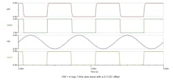
Consider this last use case in more detail. With the timer, the internal resistor divider establishes thresholds of 2/3 VDD for the high comparator and 1/3 VDD for the low compactor. In response to an input sine wave applied to the tied-together TRIG and THRESH pins, the timer will generate an inverted square wave. The square wave will be phase-shifted, with a falling edge occurring when the rising portion of the sine wave reaches 2/3 VDD and a rising edge occurring when the falling portion of the sine wave descends to 1/3 VDD.
A drawback to this approach is that the high and low threshold levels can’t be independently adjusted—they’re fixed by the internal resistor divider. In contrast, a smart DAC can be configured as a comparator with hysteresis that has two independent threshold levels programmed into registers within the smart DAC.
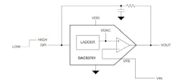
As shown in Figure 4, VOUT connects to the GPI input by way of an RC filter that suppresses noise. The smart DAC’s VFB pin serves as the input for this configuration. Figure 5 shows simulation results for a comparator with hysteresis implemented using the DAC53701.
Conclusion
Smart DACs allow you to replace discrete analog circuits and MCUs with a one-chip solution that simplifies design, reduces system cost, and offers improved performance. For low-voltage, low-output-current use cases, a smart DAC’s programmability, high accuracy, minimal requirements for external components, and stored EEPROM configuration capabilities make it a superior choice to the 555 timer.

