Learn more about UWB testing procedures and the latest developments issued by ruling bodies from around the world.
Ultrawideband (UWB) technology provides low-cost communications and measurement capabilities for a number of applications including short-range data exchange in excess of 100 Mb/s, imaging through walls and into the ground, and automotive speed and distance reporting and control. The technology for generating UWB signals generally is simple and inexpensive.
For testing UWB, five basic procedures can be used:
• Emission measurements below 960 MHz
• Emission measurements above 960 MHz
• UWB bandwidth and center frequency
• Emission measurements in GPS bands
• Measurement of peak emission in 50 MHz band
Emission Measurements Below 960 MHz
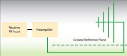
The typical test setup is identical to that for testing intentional radiators per ANSI C63.4-2003. The measurement distance is 3 meters, the antenna is raised and lowered from 1 to 4 m, and the EUT is rotated through 360• to maximize emissions. If the UWB transmitter center frequency (fC) is located below 960 MHz, great care must be exercised in locating and maximizing emissions from the EUT antenna (Figure 1).
Emission Measurements Above 960 MHz
As the measurement frequency increases above 960 MHz, the antenna factor increases, the cable loss increases, and the instrument noise floor increases. All of these factors point to the need for additional gain and measurement distances shorter than 3 m. At all times, however, the distances must remain in the far field of the measurement antenna and the EUT antenna. The far-field boundary D can be calculated from:
where: d = the largest dimension of the
frequency measured
For wideband horn antennas, the value of D can exceed 3 m below 18 GHz. For standard-gain horns in the 40- to 100-GHz range, the near-field boundary can range from about 1 m down to 30 cm.
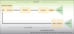
Emission maximization is performed in the same manner as for emissions below 960 MHz except that even more care must be taken to locate and maximize narrow lobes. To do that, the horn antenna may need to be aimed and moved manually around the EUT prior to a final scan. To minimize the lengths of the measurement cables, the spectrum analyzer is brought near and behind the measurement horn antenna (Figure 2).
Without the use of external preamplifiers, valid measurements could not be made in the frequency bands above 960 MHz. Consider the case of an emission limit of -63.3-dBm equivalent isotropically radiated power (EIRP) at 1,000 MHz. This is equivalent to 32 dBmV/m at 3 m. A good spectrum analyzer will have a noise floor at 1-GHz and 1-MHz resolution bandwidth (RBW) of approximately 17 dBmV. The detection limit for a 10-dB margin above the noise floor is:
Limit = analyzer noise floor + antenna factor + cable losses + 10 dB
Limit = 17 dBμV + 27.3 dB/m + 2 dB + 10 dB = 56.3 dBμVThis detection limit is 24 dB above the UWB regulatory limit shown. Even if we discard the 10-dB margin, we still cannot make the measure-ment. A preamplifier gain of about 30 dB is needed.
The additional gain above the 24-dB deficit is needed to overcome the preamplifier's own noise figure. Noise figure is the increase in noise power of an amplifier or other device from the input to the output that is greater than the signal gain.
Because preamplifiers have their own internal noise, adding gain to the measurement chain also increases the noise floor of the system; subsequent (cascaded) preamplifiers amplify the noise, too. The cascaded noise figure is affected most profoundly by the noise figure of the first preamplifier in the chain.
UWB Bandwidth and Center Frequency The UWB bandwidth must be measured to confirm that the transmitter qualifies for treatment under Part 15 subpart F rules. That is, the highest frequency (fH) minus lowest frequency (fL) >500 MHz or the fractional bandwidth >0.2. Also, the UWB bandwidth must lie fully within the frequency limits set in the individual subpart F sections such as 15.510 and 15.511.The measurement setup for fH and fL is determined by whether the frequencies are above or below 960 MHz. Because the frequency span between fH and fL is so large in UWB systems, care must be taken in measuring these -10-dB points to fully account for any frequency-dependent variations in the system, such as antenna factor and cable loss.
Once fH and fL have been accurately determined, the fC can be calculated from:
fC = (fH + fL)/2
Now the highest measurement frequency can be determined from the higher of 15.33(a) or fC + 3/(pulse width in seconds).
Emission Measurements in GPS Bands
The measurement setup for frequencies >960 MHz is used in global positioning system (GPS) bands. A 1-kHz RBW and rms average detector are selected on the spectrum analyzer. A preamplifier will be required to provide some margin above the noise floor of the system. Radiated emissions should be maximized as in ANSI C63.4-2003.
Measurement of Peak Emission in 50 MHz Band
This measurement is centered on the frequency of the highest emission (fM). Depending upon the UWB band, fM may lie either above or below 960 MHz so the appropriate test setup must be selected. Preamplification may not be needed; but if it is used, precautions should be taken to avoid signal overload and the consequent limiting and spurious emissions. As with all other measurements, the EUT must be rotated and the antenna raised and lowered to maximize the reading.
Special Challenges
Through-Wall Imaging Systems
As a slight departure from the normal test setup per ANSI C63.4-2003, through-wall imaging systems are tested for compliance using a 0.5-inch thick panel of gypsum or drywall placed between the UWB transmitter antenna and the measurement antenna. Emissions maximization should be performed in accordance with ANSI C63.4-2003 procedures.
Ground-Penetrating Radar
Evaluation of ground penetrating radar (GPR) requires the use of a sandbox, a 20-inch deep pit of dry sand at least as large as the footprint of the GPR transmitter. No ground plane is to be located at the bottom of the pit.
The GPR transmitter should rest above the surface of the sand in its normal measurement position. To maximize emissions, the GPR transmitter must be rotated through 360• in small increments as the measurement antenna is raised and lowered 1 to 4 m.
Any horn antenna should be pointed in the direction of the radiating head of the GPR transmitter. This is consistent with ANSI C63.4 Section 8.3.1.2, which states that the antenna must be kept within the cone of radiation and pointed at the area of the EUT. If absorbing material is placed between the GPR transmitter and the measuring antenna, the FCC requires 4.7 dB be added to the measurement result to correct for the absence of reflections.
Recent Developments
Changes in FCC Rules
When the FCC released the first version of its Part 15 UWB rules on April 22, 2002 (FCC 02-48), it noted that it was proceeding cautiously and would be reviewing the results within one year. The FCC next released revisions on March 12, 2003 (FCC 03-33). These new rules relaxed some UWB operating restrictions but made no major changes in emission limits.
On Dec. 16, 2004, the FCC released clarifications to its UWB rules (FCC 04-285). This document clarifies some of the operating requirements for vehicular radar transmitters, and amends measurement procedures to permit frequency hopped, swept frequency, and gated systems to be measured in their normal operating modes instead of hopping or sweeping stopped. At the same time, the FCC established limits under Part 15 subpart C for wideband devices operating in the 6- to 7-GHz, 17-GHz, and 23- to 29-GHz bands, limits similar to UWB limits.
On March 10, 2005 (FCC 05-58), the FCC waived its UWB measurement procedure requirements for indoor or hand-held devices operating outside of the 5,030- to 5,650-MHz band. This extends the allowance for UWB devices to be tested in normal operation to additional device types.
Canadian Consultation
Canada has not yet established rules for unlicensed UWB operation, but the groundwork is being laid to do so. In February 2005, Industry Canada published a UWB survey and invitation to comment, Consultation Paper on the Introduction of Wireless Systems Using Ultrawideband Technology• (SMSE-002-05). The paper reviewed wireless technologies and UWB activity around the world and raised some of the technical considerations with UWB.
EU Standards
The European Telecommunications Standards Institute (ETSI) has published two technical reports on UWB technology and followed up with two standards intended for harmonization under the R&TTE Directive. The technical reports are:
• ETSI TR 101 994-1 V1.1.1 (2004-01) Technical Characteristics for SRD Equipment Using Ultrawideband Technology (UWB) Part 1: Communications Applications
• ETSI TR 101 994-2 V1.1.1 (2004-11) Technical Characteristics for SRD Equipment Using Ultrawideband Technology (UWB); Part 2: Ground- and Wall-Probing Radar Applications; System Reference Document
These are excellent market and technology survey documents. The two standards published by ETSI are:
• Draft ETSI EN 302 066-1 V1.1.1 (2004-11) Ground- and Wall-Probing Radar Applications; Part 1: Technical Characteristics and Test Methods
• ETSI EN 302 066-2 V1.1.1 (2004-11) Ground- and Wall-Probing Radar Applications; Part 2: Harmonized EN Under Article 3.2 of the R&TTE Directive
The EN 302 066 family of UWB draft standards adopts measurement parameters and test setups very similar to the FCC UWB rules: -10-dB points for fL and fH, a dry sand pit, and a deactivation mechanism. However, there also are significant differences: UWB defined as spanning one or more decades in frequency, an allowed UWB band of 30 MHz to 12.4 GHz, and unwanted emissions based on CISPR 22 but expressed in terms of equivalent radiated power (erp).
Global regulatory compliance has always been a challenge for vendors of radio transmitters, and it appears that UWB will be no exception.
About the Author
Roland Gubisch, Ph.D., chief engineer for EMC and telecommunications at Intertek ETL SEMKO, has served as an engineering manager and quality manager since joining the company in 1990. Outside of Intertek, Dr. Gubisch is a member of the IEEE, NFPA, and IEEE Communications and EMC Societies and previously was the vice president of the U.S. Council of EMC Laboratories (USCEL) and a delegate to TIA subcommittee on harmonization of United States and Canadian telecom regulations. His education includes a B.S.E.E from Northwestern University and a Ph.D. in physiology from Cambridge University. Intertek ETL SEMKO Division, 70 Codman Hill Rd., Boxborough, MA 01719, 800-967-5352, e-mail: roland.gubisch @intertek.com
FOR MORE INFORMATION
on FCC Part 15 Subpart F
www.rsleads.com/506ee-191
on UWB technology in Canada
www.rsleads.com/506ee-192


