This is the second article in a two-part series discussing EMC test planning. The first article, which appeared in the May Issue of EE, focused on establishing test objectives and pretest requirements covered Steps 1 and 2. Part 2 concludes with Steps 3, 4, 5.
Essentially, five separate steps are involved in performing an EMC test regardless of whether it is for design/development or for formal acceptance:
1. Establish the test objectives.
2. Do a pretest requirements analysis.
3. Perform the testing.
4. Evaluate the results.
5. Correct any problems.
All five steps are interlinked. This article focuses on performing the tests, evaluating the results, and correcting any problems found.
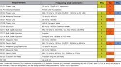
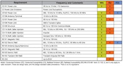
The test procedures for the various EMC tests listed in Table 1 are provided in MIL-STD-461E/F and the appropriate EU EN/IEC documents. The military and commercial EMC tests are very similar because of the way the procedures evolved.
3. Perform the Testing
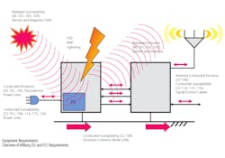
The four most important EMC tests are the conducted and radiated emissions and conducted and radiated susceptibility tests (CE, RE, CS, and RS). These form the core of all the EMC requirements called out for all equipment. If a system meets these, it has a great chance of meeting all the other requirements with the possible exception of ESD. Without prior knowledge to the contrary, these four tests would be the principle ones used for design/development testing.
Every electronics company needs some minimum EMC testing capability. In-house design/development test capability can provide circuit and packaging designers with quick feedback regarding EMC problems. It also enables them to play what-if games by quickly checking out the effects of design and troubleshooting changes.
Even though in-house design/development tests may only require a day or two, it can take weeks to arrange for and complete the testing at an outside EMC test laboratory. Problems add to the time required. A month of lost development time out of a 12- to 15-month product design-turn negatively impacts both profit and sales, and the financial impact will more than pay for the small investment in test equipment required to do in-house EMC design/development testing.
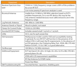
Because of the similarity between the various standards and the use of standardized test equipment, it is possible to provide design/development test capability at a reasonable cost. Table 2 provides a list of suggested equipment along with comments.
Expect to do some retesting. Even the best designers implementing the best design techniques often are disappointed with the EMC test outcome. Based on experience, the probability of initial compliance typically follows Pareto’s Law; that is, only about 80% pass. The other 20% fail and sometimes very spectacularly. This necessitates a retest often enough that it may as well be planned for in advance.
Testing laboratories fall into two different camps: 80% simply providing data or a report which says the EUT failed and the other 20% with experts on staff to help solve the problems. The choice of lab depends primarily on how much EMC test equipment is available at the EUT manufacturer’s location.
How long it takes to do the retest depends on which procedures are retested. But the time will take anywhere from 30 minutes to an hour per line for a conducted test and eight hours or more if radiated susceptibility testing has to be redone over a wide frequency range.
Times will vary from lab to lab depending on the test equipment and personnel. For larger EUTs with multiple cables, multiple modes, and multiple antenna locations, each test time will be multiplied by those factors. For example, for the radiated tests, an EUT with two modes and three antenna positions will require six times longer to do the test.
Testing that will be performed at an outside EMC testing laboratory will require considerably more effort. If the EUT is a small non-RF device, has nondescript power requirements, doesn’t contain electro-explosive devices (EEDs), and sits quietly on the ground reference plane, almost any lab can test it.
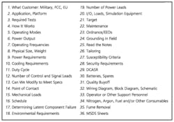
Table 3 is a listing of the EUT information that laboratories ask for when preparing a quote. This information helps them decide if their facilities will be able to handle the EUT, and it should help the test planner with the task of assembling the information required for doing the test.
Table 3. EMC Test Planning
The EMC test planner has to provide the outside laboratory with:
• The desired schedule.
• The requirements to be met and any necessary test procedures. Be sure to let the lab know of any approved specification tailoring, deviations, or waivers.
• A description of the EUT. This information should include where it is used, what it does, how it is used, what the power requirements are, and any special input/output requirements. Also, include a block diagram and the frequencies of any clock or local oscillators. If it’s a big item and not easily transported to the test lab, some labs can come to the location of the EUT. Not every lab can do that, and the RF ambient is not likely to meet the specification requirements, which typically is 6 dB under the limit.
• How the EUT is set up on the ground plane or test stand, and how it’s grounded if applicable. For commercial EMC tests, the EUT typically is set up on a test stand on a rotating turntable 80 cm above the ground reference plan. Military tests are set up directly on a stationary ground plane with the worst-case emissions side facing the front.
• How and who will operate it.
• How the operation will be monitored; what is required to show that it’s working properly.
• The pass/fail criteria. This may differ depending on the mode of operation and is decidedly different for military and commercial equipment.
• Procedures to follow if it fails. Is there a stop-test criteria? What is expected of the laboratory?
• Desired report information such as full, summary, or raw data. Is there any special information that is needed to evaluate the EUT?
• The EUT and any special cables, connectors, interface devices, and monitoring equipment.
There are some horror stories regarding the difficulty of being able to repeat EMC tests because of the large variations that arise during testing. Many of these stories are true, but this is principally only an issue with radiated tests, especially at the higher frequencies, where EUT geometry and relative position, cable layouts, and routing may change from one test time to another at a later date. For that reason, mark cables with masking tape and markers and take many photographs of test setups to enable future tests to be duplicated as closely as possible.
4. Evaluate the Results
Did the EUT pass or fail? With commercial EMC test requirements, it’s mostly cut and dry. If the EUT emission isn’t at least equal to or below the limit, it will be difficult to convince the authorities that the unit passed.
Most also know that the EMC measurement equipment will, in general, have a minimum 2- to 3-dB error (for radiated measurements the error is even greater) and that any data point that lies on the limit line has a 50% probability of passing or failing. To make matters worse, some are even aware of the CISPR 16 requirement that says multiple EUTs must pass statistically with an 80% probability using 80% K distribution or, if there is only one test sample, that it must pass with a 6-dB margin.Overview of Military, EU and FCC Requirements
MIL-STD-461 and its derivatives also require a 6-dB EMI safety margin. But for military equipment, limit tailoring up or down is permitted to arrive at a cost-effective system that will meet mission requirements and function properly in the operational EM environment.
To be clear about tailoring, this is an adjustment to the requirements that is determined at the start of a design/development program, or even during the proposal effort, based on the system analysis, the RF environment, and measured data. It is not something that is done after EMC testing by shifting the limit line so the unit passes.
If there are any discrepancies that show up during the test, they may or may not be acceptable as is. It will depend on whether or not the energy that caused the out-of-specification reading impacts the operation of the platform. If that is the case, the problem will need to be corrected. Otherwise, for a MIL-STD-461 test program, this is where waivers are requested.
In a simple system where operation can be considered steady-state, evaluating the results of emissions and susceptibility levels is straightforward. In a complex system that energizes a number of different types of circuits during its operation, evaluation is not nearly so easy.
An analysis or extended testing may be needed to assure that the EMC emissions test receiver was tuned to the pseudorandom frequency at the time the circuit produces it. A spectrum analyzer with a peak hold function can be used for this test.
The opposite problem occurs during susceptibility measurements where it’s necessary to have the RF generator tuned to the upset frequency with the appropriate modulation characteristics at the same time that the EUT circuit with that problem is on. Because of the complexity of the test situation, it can only be concluded that the EUT was tested correctly and in accordance with the test requirement/procedure and it passed. No guarantees can be given regarding its operation in the actual operating environment. EMC failure happens!
To further complicate the evaluations, radiated emissions measurements may be made in a shielded enclosure or anechoic chamber, on open area test sites (OATS), or in the vacant office down the hall. Tests in a shielded enclosure or a shielded anechoic chamber generally are preferred to OATS tests because it’s easier to segregate and isolate support and test equipment and simultaneously reduce the local RF ambient.
When using an OATS, it is necessary to determine if the signals being measured actually are coming from the EUT and not from some local radio station, welder, or manufacturing operation. Turning the EUT on and off helps as does moving the sensors close to the EUT and watching the behavior of the signal. Signals usually will increase if coming from the EUT and remain relatively constant if from the ambient.
Radiated and conducted susceptibility tests are problematic because of the difficulty in determining EUT malfunctions. Did it really fail? Is it passing when it should be failing?
As long as the EUT is humming along doing it own thing, no one ever questions its operation. It is only when it fails that test agencies are asked: Are you sure that’s really a susceptibility? Is the EMC test equipment calibrated? Have you ever run this test before? Is your test setup correct? The answer is always yes, yes, yes, and yes.
If during a susceptibility test the EUT isn’t performing exactly the same way it was before the susceptibility signals were applied, then the EUT is susceptible. Whether this is a failure or not depends on whether the customer will buy it as is. The military wants to know if this problem will impact cost, delivery, user performance, and mission success and makes the final determination based on the answers to these parameters.
The EU requirements handle the pass/fail criteria by dividing the susceptibility performance criteria into three groups:
•A: The EUT operates as intended with no performance degradation or malfunctions below the manufacturer’s minimum stated performance level.
• B: The EUT may suffer performance degradation or malfunctions below the manufacturer’s minimum stated performance level during the test but must continue to perform properly after the test with no change of state or loss of stored data.
• C: The EUT may suffer temporary degradation, malfunctions, and loss of function during the test so long as it is not permanently damaged and is either self-recoverable or can be restored by operation of its controls.
After evaluating each CE and RE and CS and RS and ESD at all frequencies, locations, and modes of operation, with luck all the EMC work is finished. All criteria are within acceptable limits, the customer requirements are satisfied, and we can pack up and leave.
Unfortunately Murphy’s Law applies, so hope for the best and plan for the worst. That is why there is a Step 5.
5. Correct Any Problems
Sometimes the EUT fails to pass the test, and the failure is not one that the customer is willing to accept. If this is a design/development test, it’s generally a simple matter to make a few changes in the lab and try again. If this is an acceptance test, then there is a major problem, and everyone now knows that inadequate EMC test planning took place in the beginning of the design/development program.
It is not enough to know that there is a problem. Designers need to know why or they cannot develop a solution to this or similar problems in the future. Sometimes the problem is a test procedural issue. Nevertheless, it has to be eliminated. After that begins the hunt for the cause, what must be changed, and who gets blamed.
If the problems are conducted-only, then the solution may simply be the addition of line filters. These may be power line filters which generally have a significantly different input and output impedance or control/signal line filters which have reasonably similar input/output impedances. If the problem is radiated, then both conducted and radiated coupling must be addressed because all radiated problems start somewhere as a conducted signal.
Radiated coupling results in a large list of things that can be manipulated to solve the problem:
• Changing operational software.
• Changing the packaging design.
• Changing PCB circuit coupling/layout.
• Redoing interface design and layout.
• Altering the grounding and bonding.
• Adding shielded enclosures.
• Power supply emissions and common impedance coupling.
• Imposing cable design restrictions.
• Adding power, control, and signal line filters.
All of these changes occur after the fact when there is the greatest cost associated with making the change, which makes up-front EMC design and design/development testing so important. It is much better to use preventive measures than try to correct the problems after the EUT is ready for manufacture.
Just implementing the following design practices from the beginning will prevent most EMC problems and reduce the work associated with Step 5. If nothing else is done, at least do these:
• Slow down. Don’t process data any faster than is necessary. If fast logic is required, slow down transitions. Change to slower logic families for I/O circuits.
• Design for zero net current flow in shielded, balanced, isolated circuits/connectors. Always route the signal wire and its return or the power wire and its return together—twisted pair, coax, or shielded pair. Do not use the structure as the return path for the circuit.
• Keep circuit loop areas associated with high-speed/high-frequency, high-current, and sensitive analog circuits as small as possible.
• Segregate and isolate high-frequency, low-frequency, and mid-frequency circuits on the PCB and locate them with regard to connectors to minimize problem loop areas.
• Although there are a few exceptions, do not use gaps, slits, or cuts, in ground planes.
• Bond/ground all metallic items together. The DC bond resistance should be less than 2.5 m? and the RF impedance should be less than 25 ? at 30 MHz.
Following these rules generally will solve the three primary EMI problems: common-mode impedance paths, magnetic field coupling, and electric field coupling. This will make it easier to meet the EMC requirements but will not eliminate the need for good EMC test planning.
About the Author
Ron Brewer is a senior EMC/RF engineering analyst with Analex at the NASA Kennedy Space Center. The NARTE-certified EMC/ESD engineer has worked full-time in the EMC field for more than 30 years. Mr. Brewer was named Distinguished Lecturer by the IEEE EMC Society and has taught more than 385 EMC technical short courses in 29 countries and published numerous papers on EMC/ESD and shielding design. He completed undergraduate and graduate work in engineering science and physics at the University of Michigan. email: [email protected]
Published June, 2010
