EMI and Signal Noise Management in Miniature Connector and Cable Systems
Download this article in .PDF format.
Electronic interconnection designs for defense electronics, highly mobile robots, surgical monitoring devices and other embedded systems are rapidly changing. Signal speeds are increasing, and are often crammed into smaller and tighter spaces, and potential signal interference as well as crosstalk can become a technical issue. Instrument-level connections must contribute to ensuring electromagnetic compatibility (EMC), is achieved.
EMC standards specify four levels. Level 1 includes discrete components, level 2 is focused on circuit boards, OEM electronic products are addressed at Level 3, which includes electronic circuitry, power sources, motherboards, and interconnect systems. Cables extending beyond the enclosure should comply to Level 4, depending on the application.
The interconnect designers goal is also to contain any potential electromagnetic interference (EMI) that would confuse the main signal system. Connector and cable shielding is used to attenuate the radiation signals from entering the interconnection, as it bleeds off any conducted noise running on the shielding. Selecting good metal conductivity as well as insulation thickness is important for best cable shielding and back-shell technology.
Military-Specification connectors and cabled interconnections used in mission-critical and high-reliability modules for military avionics, autonomous vehicles, satellites, and soldier-worn systems are especially vulnerable to Cybersecurity issues. Surprisingly internal-signal noise management is also a key element in controlling signal integrity within one’s own system.
Standard noise and EMI control methods include isolation, grounding, filtering, balancing, shielding, signal separation, impedance control, cable design, and managing the signal/time domain. To help protect signal integrity, connector and cable harness designers are also adding back-shells and cable shields for EMI protection, as well as providing mechanical strain reliefs.
Many of the smallest cables require shielding inside and out to isolate mixed signals within the interconnection system. Do not overlook the need to directly connect cable shielding to metal shell connectors. It is important that there is a firm and direct connector ground on the board and/or the metal shell of the circuit package.
Connector sizes and metals
Micro- and Nano-sized connectors are often used with metal shells connected to braided-cable shields. The metal frequently used is Aluminum 6061 with T6 treatment for the advantages of strength and lower weight, as well as the EMI sealing. Metal shells are usually treated with electroless nickel plated at .0005” thickness, and some novel designs use stainless steel for the metal housing, and occasionally see gold plating on shells used in environmentally-hazardous environments.
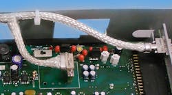
Connector shells can also use a separate metallic, back-shell covering that screws on, or is an integral portion of the connector shell (Figure 1). The back-shell is then attached to the outside shielded braid of the cable harness to finish the assembly. To ensure signal purity, miniature connectors often use beryllium-tempered spring-pin contacts, as small as 13 one-thousands of an inch in diameter, to provide constant connection through high vibration and physical shock.
Preventing poor pin-to-socket connections during vibration is critical, as they can cause signal noise and be interruptive to very high-speed digital signal transmission. Shielding within both the connectors and cable is vital to prevent EMI problems. As designers focus on higher densities and increase the number of functions, the space available for internal wire-routing of signals is getting smaller and more critical. Custom designs are more frequently employed for cabling to specifically fit within each new instrument, to reduce overall size and weight.
Circular connectors
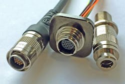
A Micro circular connector designed to work well for EMI reduction includes the Triple-thread ratcheting metal mechanism made of lightweight aluminum and provides rugged, high-reliability, watertight (IP67) connections for continuous signal integrity in harsh-environment military, aerospace, security, and petroleum applications subject to high shock and vibration (Figure 2).
Rectangular connectors
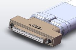
Standard Micro and Nano-d connector models should be qualified to military QPL reliability and performance specifications, and connectors with 360 degrees of sealing assure high levels of RF and Conducted interference attenuation. For example, Omnetics offers metal-on-polymer EMI shielding gaskets for special designs. Such Micro-D or Nano-D backshells are designed to protect the back end of the connector shell and provide strain relief, preventing mechanical stress for the crimped contacts, for high-reliability applications (Figure 3).
Backshells provide additional EMI protection when they are used as a grounding point for the cable shield, a ground wire, or when braiding is added over the wires. Additionally, customized backshells are designed to specific shapes and functions to aid in meeting the key design requirements or challenges. Many design formats are available for Micro-d and Nano-D connectors, including two piece solutions, straight, 45°, 90°, oval or round wire/cable exit, and with two distinct wire/cable exits.
Higher signal speeds and mixed-signal cable make for a noisy electrical environment, as the combination of electric and magnetic fields are often hard to control. Unmatched impedance in an interconnect system can cause an EMI wave that couples from cable to cable to component to element, literally killing the performance of the electronics involved. Cable design and management systems have adopted a well-defined system of solving many of these problems using cable shielding.
Cable Shielding
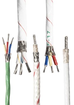
There are many types of shielded cables, and each has their own advantages and properties. A cable with an overall foil shield and unshielded twisted pairs is very similar to the common unshielded cable, the difference being the addition of foil underneath the main cable jacket. Such cables are common in 10GBaseT applications. Other cables have an overall braid shield/screen with unshielded twisted pairs. While occasionally referred to as a shielded twisted-pair cable, the two do not provide the same shielding. To identify between them check for an overall barrier and/or individual pairs’ shielding.
A cable shielding that includes both an overall braid shield and foil shield with unshielded twisted pairs are very effective at protecting EMI from entering or exiting the cable. In a cable with an overall braid shield with foil-shield twisted pairs, the shield under the jacket is a braid, and each individual pair is wrapped with its own foil barrier. The purpose of the additional foil on individual pairs is to limit the amount of crosstalk between the pairs.
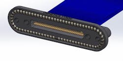
Cable shielding is becoming more common, even though not all environments require them (Figure 4). At first, shielded cables were used in spaces with high concentrations of electrical equipment and/or secure communications applications. Today shielded cables are commonly used in many spaces such as government, education, and healthcare buildings.
Cable shielding and wrapping
Wrapping conductor(s) inside the cable with EMI tape reduces the openings typically found in braided solutions. While its tradeoff is reduced flexibility, a greater level of attenuation can be obtained with the elimination of openings commonly found in braids. Typically used for high-speed applications, materials and wrap overlap are varied to change the level of shielding for the application, both internally and externally.
Generally used in high-speed applications where foil wraps or braids are not present, a conductive shrink-tube is a great option for shielding, helping control impedance in high-speed applications, or to bridge the gap between individual conductors as they exit the group braid and head to their individual locations within the connector. Values from 60 to 80db of attenuation can be obtained with a conductive shrink tube.
Signal type and cable function determines wire type, number of wires, wrapping, and insulation. Fire-wire, for example, uses a small wrapped pair of signal wires next to a single drain wire, to carry the differential signals and the ground reference. Placed over the 3-wire set is typically an aluminum shield-wrap around the bundle to isolate the signals from adjacent wiring within the cable. Adjacent wire pairs can be run within that cable to provide a power source for the instrument at the end.
If an RF set of cable is included, additional and separate wrapped aluminum shielding is needed to separate the coax from its neighbors inside the cable. Designers may consider conductive zipper or shrink sleeves, flat cable with EMI tape, and knitted-mesh shield wrapping to help with cable flex. Recently-introduced tubular metalized-fiber braid offers light weight, excellent flex, and isolation, but at higher prices with medium levels of isolation.
Shielding within both the connectors and the cable is critical to preventing EMI problems. The focus on higher density and increased functions within instruments, and the shrinking space available for the internal wire routing of signals from one section of the instrument to another, is getting more critical. Custom designs are more frequently employed for cabling to specifically fit within each instrument to reduce size and weight while increasing circuit speed, signal routing and impedance matching to other circuits in adjoining modules.
Braided shields can offer the highest isolation, but a may need a number of options or trade-offs when they can be used. Exterior cable shielding is frequently employed to assure that signals are not affected by exterior signal noise, and to contain the signals within the cable. The exterior shield is exceptionally helpful in protecting from Cyber signal threats corrupting the purpose of the cable.
Exterior cable shielding materials can vary significantly in their ability to attenuate and isolate the signals from interference. Slip-on braid is rated for up to 65 db of isolation at 500mhz and solves most concerns. As frequencies increase, the ¼ wavelength of signals is shorter and can squeeze through gaps in slide-on braiding. Designers can consider a tighter weave braid and/or a combination of both foil wrapping and slide-on braid to retain signal integrity.
For example, when isolation and signal speed demands are very high, Omnetics adds machine-wrapped braiding with plated smaller diameter copper-braided wires, delivering up to 95% coverage without small windows for signal intrusion, while being able to handle higher temperatures and extreme environmental applications. Some exterior polymer braiding materials have evolved to assist in specific areas, which include solderable plated Kevlar braids that operate to 150˚C and pass NASA outgassing specifications. Plated LCP, (liquid crystal polymer), can also be used up to 150˚C, but is solder-resistant.
Serving demanding applications
Equipment benefiting from miniature shielded wiring harnesses begin with high-performance portable systems often used in military field operations, and other applications ranging from healthcare to robotics. In the medical industry, handheld surgery tools, dental camera modules, cosmetic lasers, and even spinal pain-management tools use uniquely-designed wiring to support both patient comfort and technical performance while reducing operating-room electronic noise.
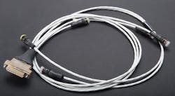
Application-specific wire-harnesses are also used in military sensor systems, processors for mine detection, portable camera and surveillance modules, and unmanned aerial vehicles (Figure 5). Today’s UAVs, faced with extreme conditions, are demanding minimum-weight miniature electronics to achieve increased payload and flight times with additional cameras, sensors, and broadcast equipment.
EMI shielding effectiveness testing is a detailed process that must meet the application needs of the cable harness. When possible, the test should list any known noise sources or frequencies the cable may be subjected to. It should also include the signal type and frequencies operating within the cable that may escape and cause trouble with adjacent electronics. Test methods often used include open field testing, which involves attempts to mimic the actual usage of the system and in what environments it will be used.
This is not done in a cage, but accomplished with a number of antennas situated about the system. When done in an open area, free-space measurements can be made of the strength and conduction of any emissions from the cable, and both noise level and EMI quantity can be detected and measured against the prime signal levels in the cable. Localized-area shield testing uses a containment box for higher-end frequencies above 500 megahertz ,to assist in measuring internal EMI from outside system EMI issues and to detect any of the higher frequency harmonics from escaping beyond the test area.
Coax line tests measure the field electromagnetic wave radiation for quantity and height of signal escape, and bending and moving the cable during testing is recommended to offer complete confidence in highly mobile systems. Coax signal and EMI testing should include both loaded and unloaded signal measurements to see the differences between the power source and the radiation under transmit and receive conditions. Shielded-room testing is often subcontracted to a specialty testing company with a metal-screened shield room where all random devices, EMI susceptibility, and emission issues can be evaluated.
For more information visit www.omnetics.com
