Instrumentation Amplifier Simplifies Audio Distortion Tests
A critical measure for all audio components is distortion, typically specified as total harmonic distortion (THD) or total harmonic distortion + noise (THD+N). THD is defined as:
where :
f1 = fundamental frequency amplitude
f2 = second harmonic amplitude
f3 = third harmonic amplitude
f4 = fourth harmonic amplitude
fn = nth harmonic amplitude (< 20 kHz)
THD+N is the rms sum of all frequency components (up to 20 kHz) divided by the amplitude of the fundamental.
However, measuring distortion has long been a difficult task, especially when figures of greater than 90 dB or more are needed. The frequency source must be of a purity exceeding the desired measurement. Plus, the analyzer's noise and dynamic range can limit the achievable resolution.
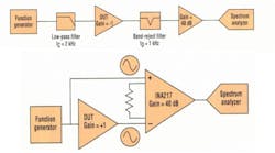
The conventional approach to this problem is described in Figure 1. A 1-kHz sine wave is passed through a low-pass filter to attenuate source harmonics greater than 1 kHz. The amplitude of the sine-wave fundamental is measured and stored as the reference level for calculations. The filtered signal is applied to the device under test, whose output is passed through a band-reject (notch) filter, removing the fundamental-frequency component. Thus, the remaining distortion components have a much smaller total dynamic range. Finally, the signal is amplified and measured with a spectrum analyzer or digitizer. After correcting for gain, the THD can be measured and calculated.
While this is an effective method, it suffers from some inherent weaknesses. The final THD can only be as good as the filtered source. Also, the filters must not introduce their own harmonic distortion and noise components. Furthermore, the notch filter must avoid attenuating the second harmonic or be calibrated to correct for this error.
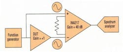
Figure 2 shows a different, simpler approach. This method takes advantage of the characteristics of a low-distortion instrumentation amplifier. These devices are differential-input, single-ended output components that subtract and amplify the difference between the inputs. Monolithic INAs have excellent resistor matching, hence good gain error and common-mode rejection. Plus, a wide range of gains are easily achieved using an external resistor. Low noise and distortion are features of products specifically designed for audio applications, such as the INA217.
The unfiltered 1-kHz reference signal is applied to the INA noninverting input, while the same signal is applied to the DUT, whose output is connected to the remaining INA input. Because the instrumentation amplifier possesses good common-mode rejection at 1 kHz (typically >80 dB), the distortion components common to the source and the DUT output are attenuated accordingly.
Because most of the signal amplitude at 1 kHz is removed, the remaining difference signal, due only to the DUT, can now be gained as needed (commonly about 40 dB) and output to the spectrum analyzer. This raises the signal above the system's noise floor by the INA gain of 40 dB.
Resolution is also enhanced by the same 40-dB gain. Moreover, the results aren't affected by the reference sine-wave purity, as source distortion components are common to both inputs and rejected by the INA. On top of that, no filters are needed.
This article was originally published on June 21, 2004.


