In the little analog computer example shown last month (April 14, p. 24), if we wanted to change the mass of the "car," we could change the feedback capacitance for A4. But it's inconvenient to adjust the value of capacitors or change around a large number of them. So instead, let's apply a pot to the input resistor.
Instead of the 100-kΩ resistor going from the summing point of A4 to the output of A3, we could have a 50-kΩ resistor going to the tap of a 50-kΩ pot, driven by A3. Or, we could have a 10-kΩ resistor going to the tap of the pot. This pot could be a 0.1% linear potentiometer—a 50-kΩ, 10-turn pot—with a turns-counting dial. These pots can still be bought for about $20, plus $20 for the dial, from Vishay-Spectrol. Now you could turn the gain up an octave, or down one or two octaves, making the "car" lighter or heavier. Similar gain adjustments could be applied to the paths for + and − damping factors at A6. (But I just used dumb rheostats.)
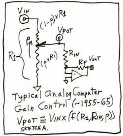
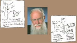
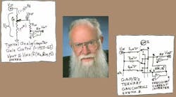
You've probably noticed that the pot setting, when the pot's wiper is loaded with a fixed resistor, will cause a nonlinear effect. To get 100% of the input conductance, you might set the pot to 100%. But to get 50% of the maximum gain, you'd typically set 63% on the pot. To get 25% or 29% of full-scale gain, the makers of analog computers—almost all of them—had special procedures for "pot setting" to some odd rotation value so the user could get the desired gain. Or, they could measure the actual gain as a function of an observed setting (sketch A). You'd turn the pot and measure the voltage at "VPOT."
George Philbrick didn't like that. He had coefficients that could be dialed in with sets of sort-of "BCD" conductances, using 12-position rotary switches. So if you didn't want 100 kΩ (10 micromhos), you could set the dials for 8 micromhos, or 9 or 11 or 22. Or 9.9 or 9.8 or 9.7, or 7.7 or 6.6 or 5.5. Or any gain coefficient between +1% and +1000%, or −1% to −1000%, or to zero. This was a very neat and NOT nonlinear gain function, even if it was kind of "digital."
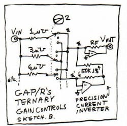
George didn't let his computers just use binary-coded input conductances. That would take four precision resistors for each decade of gain-setting. He used ternary gain schemes. For example, if you wanted to change from an input conductance of 1 micromho, to double that gain from −1 to −2, he would connect in \[3 micromhos −1 micromho\]. To accomplish this, he would put in a 333.3-kΩ resistor to one summing point and a 1.000-MΩ resistor to a precision current inverter to give a net conductance of 2.0 micromhos. Each decade needed just three resistors, such as 1 MΩ, 333.33 kΩ, 166.67 kΩ; then, 10 MΩ, 3.333 MΩ, 1.666 MΩ; and so forth (sketch B).
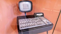
This meant that every computing function, whether summer or integrator, needed two good precision op amps per channel—one for the function, and one for the current inverter. But that's okay, because many functions needed to accept + and − inputs or provide + and − gains. The Philbrick "K5-U" computers had this feature from 1958 to 1968. The company implemented a good number of accurate summing resistors, but no tweaking of "precision pots" was ever necessary.
Comments invited! [email protected] —or:
Mail Stop D2597A, National Semiconductor
P.O. Box 58090, Santa Clara, CA 95052-8090
