Frequency mixers are often implemented using a diode bridge or a Gilbert cell. Both types of mixers use a local oscillator (LO) to flip the polarity of the radio-frequency (RF) input. When the LO is positive, the RF input passes to the intermediate-frequency (IF) output without being reversed. When the LO is negative, the RF input is reversed as it passes to the IF output. So, the LO "flips" the polarity of the RF signal. This has the effect of multiplying by +1 or 1 (neglecting losses).
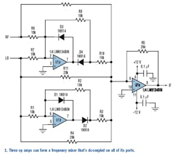
A frequency mixer also can be realized with op amps (Fig. 1). The op-amp mixer uses a square-wave LO to flip the polarity of the RF input. U1b, D1, D2, R1, and R2 form an inverting half-wave rectifier, which inverts the LO, and then outputs only the positive half of the waveform from D2. R3, R4, R5, and U1c form an inverting summer.
Because R5 and R4 are twice the value of R3, the inverted, half-wave rectified LO is added at double amplitude with the LO. Together, these components form a well-known full-wave rectifier.1 The square-wave LO input results in a negative dc output at U1c, with a magnitude equal to the level of the LO.
The remaining components, along with U1c and R5, form a variation of the aforementioned full-wave rectifier. This variation has two inputs summed at the inverting input of U1a. The RF and LO inputs are summed, inverted, and halfwave rectified. Diodes D3 and D4 are reversed from the rectifier formed around U1b, so only the negative values are output from D4.
U1c acts as an inverting summer for the RF (through R9), LO (through R11), and their inverted, half-wave rectified sum (through R10). Because R5, R9, and R11 are twice the value of R10, the half-wave rectified sum is added at double amplitude with the original RF and LO signals. The resulting waveform has a positive dc bias equal to the magnitude of the LO. Combining this result with the negative dc voltage developed by U1b and U1c cancels the two dc terms, and the desired waveform has a zero dc bias.
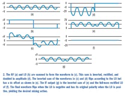
The waveforms of Figure 2 show that the IF output is the same as the RF signal when the LO is positive, but the IF output's polarity is flipped whenever the LO is negative. This is the desired mixing action.
To avoid distortion, the LO amplitude must be greater than the RF amplitude. Also, twice the sum of the LO and RF must be less than the power-supply voltage to avoid clipping. Of course, a single 10-kΩ resistor may be substituted for the parallel combination of R4 and R11. The mixer circuit can be summarized in the following equation:
IF = \\[RF + LO 2 × HALF(RF + LO) + FULL(LO)\\]
When LO > 0, this becomes:
IF = -\\[RF + LO- 2(RF + LO) + LO\\] = RF
When LO < 0, this becomes:
IF = -(RF + LO -0 -LO) = -RF
where HALF(RF + LO) represents the positive half-wave rectification of (RF + LO), and FULL(LO) represents the full-wave rectified LO, and the magnitude of the LO is greater than the magnitude of the RF. So, IF = RF when LO > 0, and IF = -RF when LO < 0.
This op-amp mixer offers several advantages. It is dc coupled on all three ports, which could be an advantage for some applications. A diodebridge mixer has transformers in the RF and LO ports. Therefore, only the IF is dc-coupled. Gilbert-cell mixers are usually ac-coupled through capacitors.
Second, the diode-bridge mixer requires an LO large enough to turn on two diodes. The op-amp mixer doesn't have this requirement. The LO can be small, as long as it's greater than the RF. Third, the op-amp mixer doesn't have the 6-dB loss found in a diode bridge mixer.
Fourth, the op-amp mixer doesn't use transformers, so it may be suitable for implementation on silicon. Finally, it features high input impedance and low output impedance, as found in most op-amp circuits.
This mixer's biggest disadvantage is its slow speed. It's useful only at low frequencies. However, fast op amps and good construction techniques may extend the frequency range. Precision resistors are required for good results.
Reference:
- Irvine, Robert G., Operational Amplifier Characteristics and Applications, p. 174-176


