This file type includes high resolution graphics and schematics when applicable.
“Tin whiskers” is not an imaginative, fanciful term for some obscure aspect of electronics manufacturing. Tin whiskers are real, microscopic conductive fibers emanating from pure tin surfaces, and they pose a serious problem to electronics of all types. Almost invisible to the human eye and 10 to 100 times thinner than a human hair, they can bridge fairly large distances between electrical device leads.
Related Articles
- Stubble Trouble--Beating Back Those Tin Whiskers
- Tin Whiskers: Avoid Stubble Trouble
- Giving Stubble Trouble The Brush Off
When a whisker grows between two conductors, it usually “fuses” (disappears), creating a momentary short circuit. In some cases it forms a conductive path, creating false signals at an incorrect location that can, in turn, cause improper operation of the device in question. They can grow fairly rapidly. Incubation can range from days to years, and there is no set timetable for when they commence growing. In very rare cases, rather than disappearing like a fuse link, the whisker can instead form conductive plasma capable of carrying over 200 A.
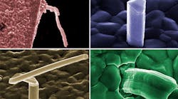
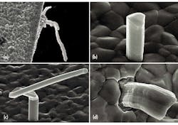
A tin whisker is generally a single crystalline filamentary surface eruption from a metal surface, though polycrystalline filamentary surface eruptions have been observed. Whiskers are usually thin, metal films, 0.5 to 50 μm, that have been deposited onto a substrate material. A typical whisker is 1 to 5 μm in diameter and between 1 and 500 μm long. Whiskers can be straight, kinked, or even curved (see the figure). Metallic film deposits have also shown other types of eruptions that are quite different in appearance from the whisker eruption. These eruptions are known as flowers, extrusions, and volcanoes.
Tin Whiskers And RoHS
Tin whiskers are relevant to today’s engineers and OEMs because they are a result of switching to lead-free electronics. The use of lead (Pb) has been banned in Europe since 2006 by the 2003 Restriction of Hazardous Substances Directive 2002/95/EC (RoHS). Although it originated in Europe, the directive now affects virtually every piece of electronics gear manufactured today or planned for the near future.
Connectors, passive and active components, switches, and relays all now must be lead-free. European safety agencies determined that it was necessary to prevent lead from entering landfill dumpsites because it is a hazardous substance. Lead is recognized as a neurotoxin known to inhibit hemoglobin production and affect brain development. Children are more at risk than adults. The removal of lead from paint and gasoline has measurably improved our environment.
As a result of RoHS, pure, tin-plated electronics have become ubiquitous in modern society over just the past five years. These electronic systems are the backbone of our communications and financial systems, our manufacturing and transportation systems, and, of course, our power plants (nuclear and conventional). In these critical systems, tin whiskers have created conductive paths and other kinds of destruction in unintended places.
RoHS is not quite all-embracing. Because of the potentially dangerous and unpredictable risks of pure tin, it is not presently used in medical devices. Lead is allowed for use in external medical devices until 2014 and for internal medical devices until 2021.
Nevertheless, apart from the medical exemption, the RoHS directive forced most electronic part manufacturers to replace their traditionally used tin-lead finishes to lead-free finishes. Since changing the finishing metallization on the components from tin-lead alloys, tin electroplating has become the most common method because of its good wettability, reliable solder joints, corrosion resistance, low cost, and ease of storage. However, it soon became obvious that these platings form whiskers easily.
There have been several incidents relating to Boeing 787 airliner electrical systems. In December 2012, a short circuit and electrical arcing were caused by a fault in a module that controlled a generator and plugged into the power panel of the motherboard. It caused the cockpit instruments to indicate that one of the plane’s six generators was down.
Subsequently, there were incidents involving lithium-ion (Li-ion) batteries in a backup power system and an emergency locator beacon on the Boeing 787. There is also speculation that the 2013 Super Bowl blackout was due to a blown underground transformer that had tin whisker shorts through the oil separating high-voltage bus bars in the transformer.
Before RoHS
Metallic whisker formation first became of widespread interest to the scientific community immediately after World War II. In 1948, the Bell Telephone Corporation experienced failures on channel filters used to maintain frequency bands in multi-channel telephone transmission lines. Bell Laboratories quickly initiated a series of long-term investigations into whisker formation, the results of which were first reported in 1951 by K.G. Compton, A. Mendizza, and S.M. Arnold.1
This Bell Laboratories work established that whisker formation occurred spontaneously on cadmium, zinc, and tin electroplating. The Bell Labs experiments studied a variety of substrate materials including copper, copper alloys, steels, and nonmetallic substrates.
One reason why the problem of tin whiskers has not yet been solved is the lack of appropriate analytical tools to study the basic structure of the tin film. Only in recent years have tools like focused ion beam (FIB), synchrotron X-ray diffraction, and electron back scattering beam (EBSD) become available for researchers to use in investigating this problem.
Induced Failures
With present circuit geometries so much smaller than they have been in the recent past, adjacent whiskers can easily bridge spaces between leads. Alternatively, whiskers from adjacent areas can touch each other, causing short circuits. In addition to causing shorts, loose whiskers can bridge board traces, foul optics, or jam microelectromechanical systems (MEMS).
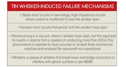
In earlier technologies, circuit voltage and current levels would almost instantaneously vaporize any whiskers, and the circuit would not even notice the event. However, low voltage and current levels in modern circuits do not have the energy needed to melt the whiskers, so circuits stay shorted by the whiskers (see the table).
No known test can accurately determine a plating technology’s propensity to generate whiskers. The stratification of electronics manufacturing gives system integrators only limited insight into the materials that are being incorporated into their products.
For example, just-in-time (JIT) manufacturing and the use of commercial-off-the-shelf (COTS) parts are common practices. JIT allows parts to be directly incorporated into systems with little or no inspection. COTS parts typically have very few restrictions on materials. Suppliers may not even be required to provide any prior notice for changes in materials or processes.
How Tin Whiskers Form
There have been contradictory opinions about the formation of tin whiskers. According to the latest information, the lead-frame material or substrate has a major impact on whisker formation. This has been one of the factors causing confusion and inconsistent conclusions.
Another factor that seems to influence results is the use of matte versus bright tin finishes. (In general, matte tin films seem to be less prone to whisker formation and growth than so-called “bright” tin films.) Many current suppliers claim that a proprietary version of matte tin is whisker-free, but these claims may be premature and should be considered carefully before use. In reporting and analyzing results, all pertinent information should be noted including, but not limited to, the type of tin used, lead frame material, and any underlay material.
The driving force behind tin whisker formation is stress in the tin film. Such stress may come from the “as plated” (i.e., not reflowed) film with its associated texture. However, the stress can also come from inter-metallic formation or mechanical operations, such as bending, forming, thermo-mechanical stresses, or possibly oxygen diffusion and/or oxide formation on the surface. The corrosion of the tin itself is another possible source for the stress in the finish. Compressive stresses are fundamental to all whisker formation.
In many cases the driving force behind a reaction, e.g., a compressive stress, can be eliminated or reduced by diffusion-based relaxation mechanisms. However, there are some cases where the driving force is not relieved by diffusion or other solid-state mechanisms, and it is even is possible that the driving force can be continuously regenerated or renewed. That is, inter-metallic formation, oxide reactions at the film surface, temperature cycling, and certain kinds of constant mechanical clamping are all conditions where the compressive stress is continually regenerated or is undiminished by solid-state mechanisms.
Stress, however, is a necessary but not in itself sufficient condition for whisker formation. It appears that there must also be a specific type of crystalline microstructure present. Researchers have also noted variations in whisker “incubation times” that range from minutes to decades. This variation is believed to be due either to the mechanisms involved in nucleating these specialized crystalline microstructures and/or the time required to build up sufficient compressive stress in the tin films. If the film stress levels are maintained at a high enough compressive level for a long enough period of time, there will be a very high likelihood of a whisker being formed as a means of relaxing the stress levels within the film beyond what can be accomplished by simple diffusion.
Further, based on tests, another major cause of stress that may result in whisker formation is the irregular growth of the Cu6Sn5 intermetallic that is created when tin is plated on copper-based substrates. (Broadly speaking, Cu6Sn5 is a from of bronze, but in the context of tin whisker formation metallurgists refer to it as an intermetallic.) Cu6Sn5 forms readily in the tin layer on tin-plated copper surfaces at room ambient temperatures. In fact, it is the dominant intermetallic at temperatures below 60°C.
The growth of Cu6Sn5 creates compressive stress in the tin layer. There are two contributing factors. First, at any temperature, the diffusion of copper into tin proceeds through grain-boundary diffusion and forms intermetallics.At room temperature, the primary intermetallic is Cu6Sn5, and grain-boundary diffusion is significantly faster than bulk diffusion. This results in irregular growth of Cu6Sn5in the grain boundaries of the tin. (At temperatures well above room ambient, generally at about two-thirds of the absolute melt temperature, bulk diffusion starts to become significant.)
Second, there are two schools of thought concerning the formation of compressive stresses in the tin film in and around the copper-tin intermetallic and the tin (copper-tin-to-tin interface). If six parts of copper are mixed with five parts of tin, the resultant Cu6Sn5has a larger molar volume than the tin and copper from which it was formed. This in itself would lead to compressive stresses at the copper-tin-to-tin interface.
Alternatively, if one considers that the copper infiltrates the tin lattice sites in the tin film leaving behind open space in the underlying copper, then the overall reaction will lead to an increase in volume in and around the copper-tin-to-tin interface. This also acts as a compressive layer of tin. Furthermore, grain-boundary diffusion dominates the growth of the Cu6Sn5phase at lower temperatures. As such the interface between the tin grains and the Cu6Sn5phase is non-planar. This can also act to increase the localized compressive stresses in the tin film.
At higher temperatures, the primary diffusion mechanism changes from grain-boundary diffusion to bulk diffusion. This results in changes in the intermetallic layer:
• Cu6Sn5 formation: Somewhere above 60°C (the exact temperature has not yet been established), Cu3Sn will form from the Cu6Sn5 and will be found between the Cu6Sn5 and copper layer. Cu3Sn5 has a lower molar volume and will not add to stress in the tin layer.
• Bulk diffusion effects: Due to bulk diffusion at higher temperatures, a more regular intermetallic double layer (Cu3Sn and Cu6Sn5) will form. (This forms the basis for a strategy of mitigation by heat treating at 150°C.)
• Plating bath impurities: Impurities in the plating bath and other defects may also enhance the possibility of whisker formation. It is not understood which impurities are the culprits and the levels to which they should be controlled. Both copper and carbon appear to be impurities that make the tin film stress increasingly compressive.
• Oxide formation and humidity: The role of oxide formation is not well understood. Humidity apparently introduces stresses from the diffusion of oxygen downward from the surface. By comparison, intermetallics introduce stresses from the substrate interface towards the surface. High humidity will affect the thickness of the oxide film on the tin layer, leading to compressive stress. Impurities or defects in the oxide film may also contribute to whisker formation. High humidity might lead to corrosion, which could introduce additional stress. The relation to actual field life of these test conditions is unknown. Serious consideration should be given to storage conditions. Additionally, the high humidity may affect the tin’s surface diffusion rates.
• Condensation and corrosion: Condensed moisture exposure, either by water condensation during high-temperature humidity testing or via water droplet exposure, can lead to corrosion-assisted whisker growth. Excessive localized surface corrosion can produce non-uniform oxide growth that imposes additional differential stress states on the tin film. The combination of condensed moisture and higher temperatures has been shown to produce either localized clusters of whiskers or accelerated growth of an individual whisker. Often identified as lead termination “black spot corrosion,” whiskers found to nucleate in the corroded regions will continue to grow even after removal of the condensed moisture. Corrosion has been identified as a confounding factor in extended duration, high-humidity testing.
• Incubation time: The incubation time before whiskers form has been very unpredictable. Under high-stress conditions, whiskers have been shown to grow very rapidly. In other cases, years have passed before whisker growth has been seen at all. This may be due to the requirements for a recrystallization event to occur that creates an appropriate whisker grain, or whisker growth may be delayed due the length of time required to build sufficient stress to start the whisker formation process.
Whisker Mitigation
“Mitigation” refers to processes or materials that enhance resistance to whisker formation on tin-based films, but do not necessarily prevent their ultimate formation. Since compressive stresses are thought to be fundamental to whisker formation, mitigation approaches are aimed at altering the stress state within the tin.
The first and best option is to avoid using pure tin, but depending on suppliers, it is seldom possible. The mitigation techniques described below can be effective, but none of them havebeen proven to provide the degree of protection required by high-reliability equipment. With that caveat, here they are:
• Specify matte tin (tin with a dull low-gloss finish and larger grain size). It is more resistant to whiskers than bright tin.
• Anneal the tin after plating. This can reduce the stresses created during plating that contribute to whisker growth.
• Robotic solder dipping with tin-lead solder is said to work for some, but not all, components. Obviously, the components must be handled carefully to avoid damage during the process.
• Conformal coatings can be applied, but their success depends on the coating material, thickness, and application process.
• Some testing has shown promise for surface chemical etching prior to plating of copper-based alloys. The etching depth is in the range of 3 to 4 μm.
• Conformal coatings on circuit board assemblies can be used to reduce electrical shorting risks. Thicker coatings (≥3.9 mils) have been shown to prevent or delay whisker penetration. Thinner coatings act as a dielectric layer for whiskers that may break off in an assembly.
Reference
“Filamentary Growths on Metal Surfaces - Whiskers,” K.G. Compton, A. Mendizza, and S.M. Arnold, https://www.itri.co.uk/index.php?option=com_mtree&task=viewlink&link_id=25703&Itemid=11


