Accurately Determine Steady-State Output For A Periodically Driven RC Filter
This article is part of the Ideas for Design Series: Vol. 3, No. 9.
A recent Idea for Design showed a graphical technique for determining the output of an RC filter driven by a pulse-width modulation (PWM) pulse train.1 It requires the manipulation of infinite series with a limit. Therefore, it does not yield steady-state results with confidence.
Related Articles
- Graphically Determine The Output Signal Level Of An RC Filter
- Passive RC Filters Afford Low Cost And High Selectivity
- R-C Twin-Tee Circuit Reduces Power-Supply Hum
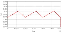
A better approach uses the concept of continuity of states and steady-state “wrap-around” to eliminate this shortcoming, since current and voltage values in a real circuit cannot change instantaneously. Current and voltage are variables with continuous values in time, from moment to moment. For a circuit structure that is switched periodically among several states repeatedly, the end state of one structure serves as the starting state of the next.
Using the same RC filter, periodic-input pulse train, and designations as the referenced Idea for Design, Equation 1 shows the filter output when the driving source VA is non-zero:
This indicates that the end state of active duration with non-zero driving source must act as the starting state, V0b, of the inactive duration with zero drive. Similarly, the end state of the inactive interval must return to the same starting state, V0a, of the active segment. Using these facts and Equations 3a and 3b, we get:
and confirms Equation 16 of the previous approach.
The approach presented here gives the true steady-state output in compact, closed form with a high degree of confidence. The technique can be extended to other second- and higher-order circuits that are switched periodically among multiple states.2, 3
References
1. “Graphically Determine The Output Signal Level Of An RC Filter,” Electronic Design, Oct. 3, 2013.
2. Switch-mode Power Converters, Keng Wu, Elsevier, 2005, ISBN 13:978-0-12-088795.
3. Power Rectifiers, Inverters, and Converters, Keng Wu, Lulu.com, 2008, ISBN 978-1-4357-2023-7.
Keng C. Wu has a BS from Chiaotung University, Taiwan, and an MS from Northwestern University, Evanston, Ill. He has published four books and holds seven U.S. patents. He can be reached at [email protected].


